17-299-01 rev. 01 1/02
CAUTION
:
NEVER USE SOLVENTS
Cleaners, fuel, paint, sealants, and other products may
contain strong solvents, such as acetone, which attack
many plastics greatly reducing their strength.
IMPORTANT
: Please read these instructions
completely before proceeding with the installation.
These directions supersede any other instructions in
your instrument manual if they differ.
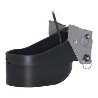
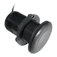
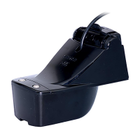
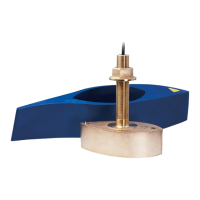
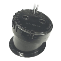
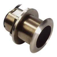
Transom Mount 1kW Depth Transducer
Models: TM256, TM260
See cable tag: Part #________________Date___________Freq._____
Applications
• Sport fishing vessels
• Good operation up to 30kn (35MPH)
•
Not
recommended for high-speed inboard powerboats
• Bracket protects the transducer from frontal impact only
Tools and Materials
Pencil
Safety goggles
Dust mask
Saw (some installations)
File (some installations)
Sandpaper (some installations)
Wrench: 3/8"
Electric drill
Drill bits:
Bracket holes 4mm, #23,
or
9/64"
Fiberglass hull chamfer, countersink, 6mm,
or
1/4"
Transom hole (optional) 19mm
or
3/4”
20mm
or
13/16"
Furuno, Raymarine only
Cable clamp holes 3mm
or
7/64"
OWNER’S GUIDE & INSTALLATION INSTRUCTIONS
Figure 1. Mounting location on single drive boat
15cm (6")
minimum beyond
swing radius
hull projection:
0-3cm (0-1/8")
Figure 2. TM256
Masking tape
Marine sealant
Screwdrivers
Straight edge
Stainless steel bolts, nuts, and washers (2 each) 6mm
or
1/4"
Zip-ties
Water based anti-fouling paint (
mandatory in salt water
)
Mounting Location
General Guidelines
• Mount on the side of the transom where the propeller is rotating
downward (see Figure 1).
• The transducer should be located so that the water passing
over the transducer does not cause a flow disturbance to the
propeller.
• The transducer
must
be submerged in aeration-free and
turbulence-free water.
Do not
mount the transducer in an area
of turbulence or bubbles: near water intake or discharge
openings; behind strakes, struts, fittings, or hull irregularities;
behind eroding paint (an indication of turbulence).
• Avoid mounting the sensor where the boat may be supported
during trailering, launching, hauling, or storage.
• Ideally, mount the bracket above the waterline to minimize the
build up of marine growth. It may be desirable to mount the
bracket farther from the keel than recommended in Figure 1.
• Allow enough headroom above the bracket for the transducer to
be raised into the “up” position and the “released” position
(see
Figure 2). If there is too little headroom, the support tube
must
be
shortened (see “Shortening the Support Tube” on page 2).
“Up” position
—The bracket is factory pre-set to provide a
vertical travel of 77mm (3") between the “up” and “down”
positions. The vertical travel can be adjusted by moving the
lower
latch pin to another set of adjustment holes. With the lower
latch pin in the
bottommost
set of holes, the support tube
requires 30cm (12") of headroom above the bracket in the “up”
position.
The upper latch pin must be inserted through the
topmost holes of the support tube for the transducer to release.
“Released” position
—The transducer makes an arc of 110
°
.
“up” “down” “released”
transducer
face
parallel to
waterline
“down”
position
sensor in