Do you have a question about the Airmar Tilted Element B164 and is the answer not in the manual?
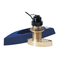
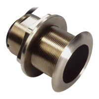
Discusses hull material compatibility for bronze and stainless steel housings.
Explains how to match transducer tilt angle to hull deadrise for optimal performance.
Safety and performance guidelines for selecting the transducer's mounting position.
Recommended mounting locations for different boat types like planing, inboard, and stepped hulls.
Step-by-step instructions for drilling holes and dry fitting the transducer housing.
Applying marine sealant to ensure a watertight seal for the transducer housing.
Isolating stainless steel housing in metal hulls to prevent electrolytic corrosion.
Securing the transducer housing, hull nut, and set screws.
Properly routing the transducer cable to prevent damage and interference.
Guidelines for applying water-based anti-fouling paint to the transducer face.
Instructions for cleaning aquatic growth from the transducer's face.
Information on ordering replacement transducers and parts using cable tag data.
Instructions for checking for leaks after installation and initial immersion.
Steps for preparing a cored fiberglass hull for transducer installation.
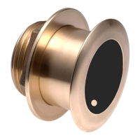
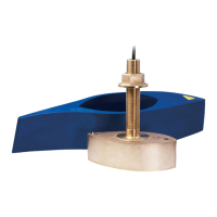
This document describes the installation, usage, and maintenance of Airmar Thru-Hull 1 kW Tilted Element™ Depth Transducers with Temperature Sensor. These transducers are designed for various hull types and come in different tilt angles to match the boat's deadrise.
The Airmar Tilted Element™ Depth Transducer is a high-performance thru-hull device designed to provide accurate depth and temperature readings for marine echosounders. It utilizes a tilted element design to compensate for the hull's deadrise angle, ensuring the transducer beam is aimed straight down, even on hulls with significant V-shapes. This design optimizes signal return and improves depth performance. The transducer also incorporates a temperature sensor for water temperature readings.
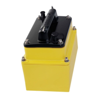
CHIRP (Compressed High-Intensity Radiated Pulse) transducer models are available, offering enhanced target resolution and depth penetration compared to traditional fixed-frequency transducers. These models require careful mounting in a cool, well-ventilated area to prevent overheating.
| Brand | Airmar |
|---|---|
| Model | Tilted Element B164 |
| Category | Transducer |
| Language | English |