Do you have a question about the Airmar TRIDUCER P66 and is the answer not in the manual?
Instructions for drilling pilot holes for mounting the bracket, including bit size and depth.
Guidance on using plastic shims based on transom angle for proper sensor installation.
Steps for applying sealant and securing the mounting bracket to the hull.
Instructions for cleaning and maintaining the speed sensor's paddlewheel.
Information on ordering replacement parts and part numbers.
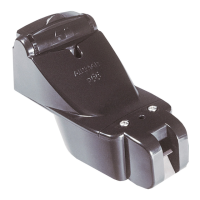
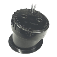
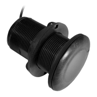
This document describes the installation, operation, and maintenance of a transom-mount depth transducer or TRIDUCER® multisensor, Model P66, with an integral release bracket.
The device is a transom-mount transducer or multisensor designed to measure depth, speed, and temperature in marine environments. It is engineered to provide accurate readings by maintaining contact with smooth water flow, even at speeds up to 44 knots (50 MPH). The integral release bracket protects the sensor from frontal impact by allowing it to rotate upward. The transducer vertically orients its sound beam on hulls with deadrise angles up to 30° and adjusts to transom angles ranging from 2° to 22°. The speed function utilizes a paddlewheel to measure boat speed, and a temperature sensor provides approximate water temperature readings.
The transducer is suitable for most boats, but it is not recommended for boats with large or twin-screw inboard engines or for stepped hulls. Proper mounting is crucial for optimal performance. The sensor should be installed in an area of clean water, free from turbulence, bubbles, or obstructions like water intake/discharge openings, strakes, struts, fittings, or hull irregularities. For single drive boats, it should be mounted at least 75mm (3") beyond the swing radius of the propeller, preferably on the starboard side where propeller blades move downward. For twin drive boats, the sensor should be mounted between the drives.
Installation involves using a provided template to mark drilling locations on the transom. The template helps align the sensor with the bottom edge of the transom and parallel to the waterline. Depending on the transom angle (standard, stepped, or small aluminum/fiberglass boats), a plastic shim may be used with the taper up or down to achieve the correct sensor angle. The bracket is screwed to the hull, and the sensor is then attached to the bracket, ensuring the retaining cover is closed and latched to prevent detachment during operation.
After installation, the sensor's angle and projection need to be checked. The leading edge of the sensor should not be lower than the trailing edge to avoid aeration. The sensor's stern should be 1-3mm (1/16-1/8") below its bow or parallel to the hull bottom, and its bottom left corner should project 3mm (1/8") below the hull. Adjustments can be made by releasing the sensor from the bracket (either by a sharp upward blow to the underside of the housing or by using a screwdriver to pry it up) and repositioning the bracket.
Cable routing is an important step, requiring careful placement to avoid damage. The cable should be secured to the transom with clamps and routed to the instrument, avoiding electrical interference from other wiring or the engine. Excess cable should be coiled and secured with cable ties.
Testing on the water is essential to verify performance. Users should gradually increase boat speed and observe the echosounder's performance. A sudden decline in performance indicates turbulent water, suggesting the sensor may be in aerated water or require adjustment. Performance can be improved by increasing the sensor's angle in the water, moving it deeper into the water in 3mm (1/8") increments, or moving it closer to the boat's centerline. For high-speed operation (above 35 knots/40 MPH), less projection into the water may be required to reduce drag and prevent the bracket from releasing. Calibration of the speed function may be necessary to match the display to the actual boat speed.
Regular maintenance is crucial for optimal performance and longevity. The transducer's surface should be cleaned with a Scotch-Brite® scour pad and mild household detergent, taking care to avoid scratches. For severe fouling, light wet sanding with fine grade wet/dry paper can be used.
Anti-fouling paint is mandatory for surfaces exposed to salt water that do not interlock, as aquatic growth can rapidly accumulate and reduce performance. Only water-based anti-fouling paint should be used, as ketone-based paints can damage the plastic transducer. Paint should be applied every six months or at the beginning of each boating season.
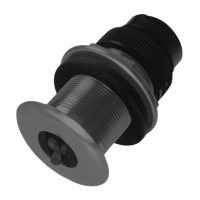
The speed sensor (paddlewheel) may require cleaning if it becomes fouled or inoperable. To clean, remove the two screws holding the speed sensor, slide it upward, and then pull the retaining bars to access the shaft. After cleaning, the paddlewheel should be reassembled, ensuring the short side of the blade is oriented correctly as shown in the side view.
Checking for leaks immediately after placing the boat in the water is critical. Users should check around all screws and drilled holes for any water seepage.
Replacement parts, such as the paddlewheel kit, bracket and wedge kit, and speed sensor kit, are available. The cable tag contains the necessary information (part number, date, frequency) for ordering replacements. The water-lubricated paddlewheel bearings have a limited lifespan (up to 5 years for low-speed boats and 2 years for high-speed vessels) and should be replaced when broken or worn. Some depth/temperature units can be upgraded by adding a speed sensor.
| Frequency | 50/200 kHz |
|---|---|
| Material | Urethane |
| Measures | Depth, Speed, Temperature |
| Power Handling | 600W RMS |
| Housing Material | Urethane |
| Type | TRIDUCER |
| Power | 600 W |
| Operating Temperature | -10°C to +50°C |
| Mounting Style | Transom |