Stepped Transom Only
If there is insufficient headroom under the step for the sensor to fully
release, remove the cover before proceeding
(see Figure 1, maximum headroom). This is necessary to access the
bracket screws at a later time.
1. Remove the two screws that hold the speed sensor onto the transducer
housing (see Figure 6).
2. The paddlewheel assembly is a loose slip fit. Carefully, slide the speed
sensor upward while keeping the paddlewheel assembly inside (see
Figure 13).
3. Insert a blade screwdriver between the cover and the transducer
housing (see Figure 7). Pry each side apart, in turn.
4. Lift the cover up and off.
Attaching the Sensor to the Bracket
CAUTION: The retaining cover must be closed and latched to
prevent the sensor from coming off the bracket when the boat is
underway.
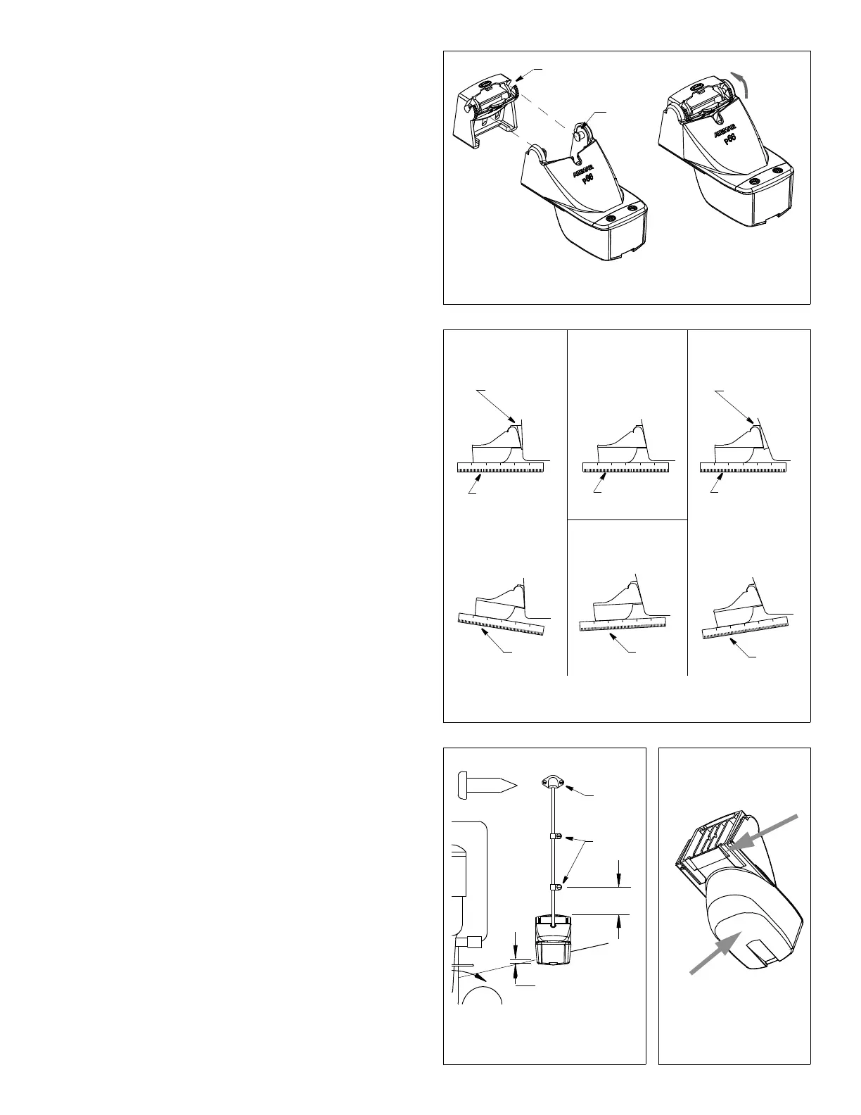
1. If the retaining cover is closed, open it by depressing the latch
and rotating the cover downward (see Figure 8).
2. Insert the sensor’s pivot posts into the slots in the top of the
bracket (see Figure 9). Push down until the posts click into place.
3. Rotate the sensor downward until it snaps onto the bracket.
4. Close the retaining cover by rotating it upward until it latches.
Checking the Sensor Angle & Projection
CAUTION: Do not position the leading edge of the sensor lower
than the trailing edge because aeration will occur.
CAUTION: Do not position the sensor deeper into the water than
necessary to avoid increasing drag, spray, and water noise and
reducing boat speed.
CAUTION: For boats capable of speeds above 20kn (28MPH)—
The trailing edge of the sensor must be deeper in the water than
the leading edge. This will ensure that the paddlewheel is in
contact with the water at high speeds.
1. Using a straight edge, sight the underside of the sensor relative
to the underside of the hull (see Figure 10). The stern of the
sensor should be 1–3mm (1/16–1/8") below the bow of the
sensor or parallel to the bottom of the hull.
2. Check that the bottom left corner of the sensor projections 3mm
(1/8") below the bottom of the hull (see Figure 11).
3. If the sensor needs adjustment, release it upward (see “Releasing
the Sensor” below). Adjust the bracket. Tighten the screws.
Releasing the Sensor
Do one of the following (see Figure 12):
• Using the palm of your hand, give a sharp upward blow to the
underside of the transducer housing. Do not hit the speed sensor.
• Insert a blade screwdriver between the transducer housing and
the bottom of the bracket (either side). Push up on the
screwdriver while lifting up on the sensor.
Attaching the Cover & Blank or Speed Sensor (some installations)
1. Spread the sides of the cover horizontally (see Figure 7).
2. Slide the cover up and over the mounting ears.
3. Push the cover down until it sits flush on the transducer.
4. Squeeze the sides of the cover until the tabs snap into the slots.
5. Insert the side rails of the speed sensor or blank into the
channels on the back of the transducer housing (see Figure 6).
Slide it downward. Fasten the speed sensor or blank in place
with the two, #6 x 5/8", self-tapping screws.
11° transom angle
12°–18° transom angle
Figure 10. Sensor angle adjustment
19° –22° transom angle2° –10° transom angle
slight
angle
reversed
angle
too steep
nearly parallel
shim with
shim with
YES
YES
YES YES
NONO
angle
taper down
taper up
NO SHIM
NO SHIM
Figure 11. Vertical adjustment
50mm
cable
cable
Hull projection
3mm (1/8")
3
Figure 12. Releasing
the sensor
Figure 9. Attaching the sensor to the bracket
close &
retaining
pivot
post (2)
slot (2)
cover
clamps
(2")
and cable routing
cover
latch
insert
screwdriver
(either side)
AB
at bevel
actual size
cable screw
give sharp
blow with
palm of hand
Copyright © 2003 Airmar Technology Corp.
Copyright © 2003 , 2010 Airmar Technology Corp.
Copyright © 2003 Airmar Technology Corp.
Copyright © 2003 Airmar Technology Corp.
nearly parallel
nearly parallel
 Loading...