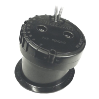
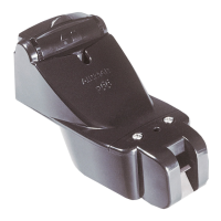
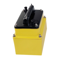
Retractable
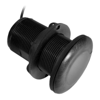
Low Profile
B17
17-006-01 rev. 07 07/07
CAUTION
:
NEVER USE SOLVENTS!
Cleaners, fuel, paint, sealants, and other products may
contain strong solvents, such as acetone, which attack
many plastics greatly reducing their strength.
Thru-hull Depth Transducer
Low Profile, Flush, and Retractable Models
Applications
•
Plastic
housing recommended for fiberglass or metal hulls only.
Never
install a plastic transducer in a wood hull, since swelling
of the wood can possibly fracture the plastic.
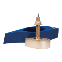
•
Bronze
housing recommended for fiberglass or wood hulls.
Never
install a bronze housing in an aluminum hull, because
electrolytic corrosion will occur.
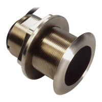
•
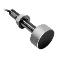
Stainless steel
housing compatible with all hull materials.
Recommended for aluminum hulls to prevent electrolytic
corrosion
provided the stainless steel housing is isolated from
the metal hull.
•
Never
install a metal
housing in a vessel with a positive ground
system.
Identify Your Model
The model name is printed on the cable tag.
Tools & Materials
Safety goggles
Dust mask
Electric drill with 10mm (3/8") or larger chuck capacity
Drill bit: 3mm
or
1/8"
Hole saw (see table opposite)
Countersink tool (installing a flush housing)
Sandpaper
Mild household detergent
or
weak solvent (such as alcohol)
File (installation in a metal hull)
Marine sealant (suitable for below waterline)
Slip-joint pliers (installing a metal housing)
Zip-ties
Water-based antifouling paint (
MANDATORY IN SALT WATER
)
Installation in a cored fiberglass hull (see page 4):
Hole saw for hull interior: (see table on this page)
Fiberglass cloth and resin
or
Cylinder, wax, tape, and casting epoxy
Mounting Location
Caution
: DO NOT MOUNT near water intake or discharge
openings, or behind strakes, fittings, or hull irregularities.
• The water flowing under the hull
must
be smooth with a
minimum of bubbles and turbulence (especially at high speeds).
• The transducer
must
be continuously immersed in water.
• The transducer beam
must
be unobstructed by the keel or
propeller shaft(s).
• Choose a location away from interference caused by power and
radiation sources such as: the propeller(s) and shaft(s), other
machinery, other echosounders, and other cables. The lower
the noise level, the higher the echosounder gain setting that
can be used.
• Choose a location with a deadrise angle of 20º or less, so the
transducer beam will be aimed at the bottom.
• Choose an accessible spot inside the vessel with adequate
headroom for the height of the housing, tightening the nuts, and
removing any insert (see the table below).
Model
Minimum
Headroom
Outside Hull
Hole Saw Size
Cored Fiber-
glass Hull Only
Hull Interior
Hole Saw Size
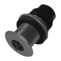
Low Profile:
P19, P319,
B117, B619
95 mm (3-3/4") 51 mm
or
2" 60 mm
or
2-3/8"
Low profile:
SS555
95 mm (3-3/4")
51 mm
or
2"
57 mm
or
2-1/4"
in a metal hull
60 mm
or
2-3/8"
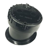
Flush:
P219, P269,
B21,
100 mm (4") 51 mm
or
2" 60 mm
or
2-3/8"
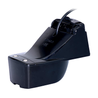
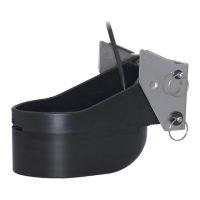
Retractable:
P217, P314,
B17, B21
200 mm (8") 51 mm
or
2" 60 mm
or
2-3/8"
Retractable:
SS577
200 mm (8")
51 mm
or
2"
57 mm
or
2-1/4"
in a metal hull
60 mm
or
2-3/8"
Record the information found on the cable tag for future reference.
Part No._________________Date___________Frequency________kHz
IMPORTANT
: Please read the instructions completely
before proceeding with the installation. These
instructions supersede any other instructions in your
instrument manual if they differ.
INSTALLATION INSTRUCTIONSOWNER’S GUIDE &
P219
Flush
Low Profile
P319