Do you have a question about the Airmar R599LM and is the answer not in the manual?
Explains how hull material affects transducer performance and the need for solid hull.
Criteria for selecting the optimal mounting spot on the hull, considering water flow and interference.
Steps to connect the transducer and check its initial performance.
Methods to test transducer placement inside the hull against the baseline.
Guidelines for marking and cutting the tank to match the hull's deadrise angle.
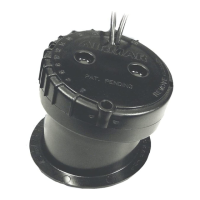
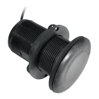
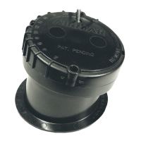
This document outlines the installation and maintenance procedures for an in-hull depth transducer, designed for 2-3kW echosounder systems. It is specifically intended for fiberglass hulls and is compatible with Chirp models R111LH, R111LM, R599LH, and R599LM.
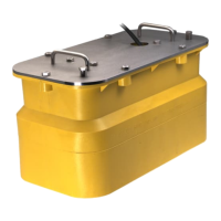
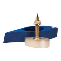
The transducer is designed to transmit and receive acoustic energy through the hull of a boat, providing depth readings for echosounders. Unlike through-hull transducers, this in-hull model does not require drilling a hole in the boat's hull, making installation less invasive. It operates by transmitting sound waves through a liquid-filled tank that is bonded to the inside of the hull. The sound waves then travel through the hull into the water, reflect off the bottom, and return to the transducer. The fill liquid in the tank, typically propylene glycol, facilitates efficient sound transmission between the transducer and the hull. The transducer is assembled with a gasket and plate, secured by bolts, and then placed within a custom-cut tank that is bonded to the hull.
The transducer is suitable for fiberglass hulls only and is recommended for high-speed boats. It can accommodate deadrise angles up to 12° on the long side of the tank and 22° on the short side. The system is designed to operate effectively in tank fill-liquid temperatures up to 60° C (140° F).
Proper mounting location is crucial for optimal performance. For displacement hull powerboats, it should be located amidships near the centerline, preferably on the side where propeller blades move downward. For planing hull powerboats, the ideal spot is well aft, on or near the centerline, and inboard of the first set of lifting strakes to ensure constant water contact at high speeds. Outboard and I/O boats should have the transducer mounted just forward of the engine(s), while inboard boats require placement well ahead of the propeller(s) and shaft(s). Stepped hulls should have the transducer mounted just ahead of the first step.
The chosen location must be free of coring material (such as foam or balsa wood), as these materials are poor sound conductors and will significantly reduce performance. The hull below the transducer must be solid fiberglass, with no trapped air bubbles, flotation material, or dead air space between the inner and outer skins. The location should ensure continuous contact with water, even at high speeds, and be free from bubbles and turbulence caused by water intakes, discharge openings, strakes, fittings, or hull irregularities. The transducer beam should not be obstructed by the keel or propeller shaft(s). It is also important to avoid interference from power and radiation sources like propellers, shafts, other machinery, echosounders, and cables. The mounting area inside the vessel must provide sufficient space for the tank and transducer, and it should be cool and well-ventilated, away from the engine, to prevent overheating of the fill liquid.
A performance baseline test is recommended before final installation. This involves temporarily lowering the transducer over the side of the boat into the water and observing the echosounder's performance. Then, the transducer is tested inside the hull at the proposed mounting location using various methods: placing it against the hull with bilge water, using a thin plastic bag partially filled with water, or applying a water-based lubricant to the active face and pressing it firmly against the hull. The goal is to find a location where the echosounder's performance closely matches the baseline, indicating efficient sound transmission.
The installation process involves marking and cutting the tank to match the hull's deadrise angle, ensuring the beam is aimed straight down. The tallest side of the tank should be closest to the centerline (keel) of the boat. A cork liner is then fitted inside the tank to reduce sound echoes. The tank is bonded to the hull using fiberglass resin or marine putty/sealant, ensuring a liquid-tight, watertight seal. After the bonding material cures, the cork liner is inserted, and propylene glycol is poured into the tank until it covers the exposed hull. The transducer is then lowered into the tank, secured with hex-head bolts and lock washers, and the tank is topped off with propylene glycol, leaving a small air space for expansion.
To ensure optimal performance and longevity, several maintenance considerations are highlighted. The transducer should always be operated in liquid; operating in air can lead to overheating and failure. It is crucial not to install the transducer in the engine compartment or other hot areas, as high temperatures can cause the fill liquid to exceed 60° C (140° F) and lead to transducer failure.
When handling the transducer, never pull, carry, or hold it by the cable, as this can sever internal connections. Solvents, cleaners, fuel, sealants, paint, and other products containing solvents should be avoided, as they can damage the plastic parts, especially the transducer's face.
During installation, the hull surface under and around the tank must be smooth, clean, and dry to ensure a tight bond. Any paint or other hull finish should be removed, and the area should be sanded with 80-grit sandpaper. The tank itself should also be sanded to promote adhesion.
When assembling the transducer, the gasket should be firmly pressed onto the plate, aligning the holes and edges. The bolts securing the plate to the transducer should be tightened using a torque wrench, not exceeding 85 in-lb, to prevent over-tightening and potential cracking of the tank. Similarly, when attaching the transducer to the tank after bonding, the bolts should not be over-tightened.
The cable should be routed carefully to the echosounder, avoiding tearing the jacket when passing it through bulkheads. Grommets should be used to prevent chafing. To minimize electrical interference, the transducer cable should be kept separate from other electrical wiring and the engine(s). Any excess cable should be coiled and secured with cable ties.
The transducer ID line can be monitored for the internal temperature of the fill liquid. If the fill liquid consistently reaches temperatures above 60° C (140° F), it indicates a potential issue with the mounting location or ventilation, which could lead to transducer failure.
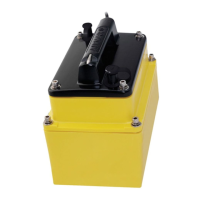
For replacement parts or transducers, the information printed on the cable tag (part number, date, and frequency) is essential and should not be removed. Lost, broken, or worn parts should be replaced immediately. If the cable needs to be cut and spliced, Airmar's splash-proof Junction Box No. 33-035 must be used, and its instructions followed, to avoid voiding the warranty. Removing the waterproof connector or cutting the cable without using a watertight junction box will void the transducer warranty.
| Power | 3000 W |
|---|---|
| Material | Bronze |
| Mounting Type | Thru-Hull |
| Housing Material | Bronze |
| Type | Broadband |
| RMS Power | 3000 W |
| Depth Range | Up to 3000 m |
| Operating Temperature | -10°C to +40°C |