Do you have a question about the Airmar P79S and is the answer not in the manual?
Follow safety and operational precautions to reduce risk of damage, injury, or death. Includes warnings about safety gear and transducer operation.
Details the suitable applications for the transducer, including hull types and boat classes, and deadrise angle accommodation.
Lists all necessary tools and materials required for the installation process, including safety equipment and adhesives.
Guides on selecting an appropriate mounting location, emphasizing solid fiberglass hulls and avoiding cored areas.
Provides specific advice on transducer placement to avoid water turbulence and interference from boat structures or other equipment.
Method to establish a baseline performance reading by testing the transducer externally before internal installation.
Procedures for testing potential internal mounting locations using different methods based on hull deadrise angle and surface condition.
Explains how to measure the hull's deadrise angle and establish a guideline for precise base alignment.
Details on aligning the transducer base flange with the hull's deadrise angle using markings and a guideline.
Instructions for joining the transducer to the locking ring and lubricating the O-ring for a proper seal.
Ensuring the transducer assembly is level after installation and checking the seating with the angle indicator.
Guidance on routing the transducer cable to the instrument, preventing damage, and managing electrical interference.
Specific instructions for installing the transducer in a cored hull, focusing on bonding the base to the outer skin.
Information on how to identify and order replacement transducers or parts, including part numbers and kits.
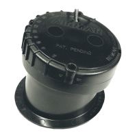
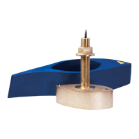
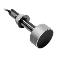
The Airmar In-Hull Adjustable-angle Depth Transducer is a sophisticated device designed for marine applications, specifically for use with fiberglass hulls. It functions as a depth sounder, transmitting acoustic energy through the hull to measure water depth and provide detailed information about the underwater environment. This transducer is suitable for a variety of vessels, including high-speed powerboats and racing sailboats, and can accommodate hull deadrise angles ranging from 2° to 22°.
The primary function of this transducer is to provide accurate depth readings and bottom imaging by sending and receiving acoustic signals. When properly installed, the transducer's active face is in direct contact with the hull, allowing it to transmit sound waves through the fiberglass into the water. These sound waves then reflect off the seabed or other underwater objects and return to the transducer, which converts them into electrical signals for interpretation by an echosounder.
For Chirp models (P75M, P95M), the transducer utilizes Chirp technology, which transmits a wide range of frequencies rather than a single frequency. This broad spectrum of signals allows for enhanced resolution and target separation, providing more detailed and accurate information about the water column and bottom structure. The adjustable-angle design ensures that the transducer's beam is oriented correctly, compensating for the hull's deadrise and ensuring that the acoustic energy is directed straight down, even when the hull is angled.
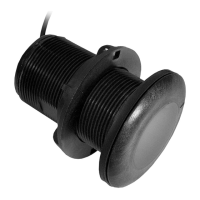
The installation process is critical for optimal performance and involves several key steps to ensure a liquid-tight seal and proper alignment. The transducer is designed for in-hull mounting, which means it is installed inside the boat, eliminating the need for through-hull drilling and reducing drag. This type of installation is particularly advantageous for high-speed vessels and those where minimizing hull penetration is desired.
A crucial aspect of using this transducer is selecting the correct mounting location. The manual emphasizes choosing a spot where the fiberglass hull is solid, free from air bubbles, coring material (such as foam or balsa wood), or dead air spaces, as these materials can absorb acoustic energy and degrade performance. The ideal location is where the hull is consistently in contact with water, even at high speeds, and where water flow is smooth with minimal turbulence. It should also be positioned away from sources of electrical interference, such as propellers, shafts, other machinery, or other echosounders. The transducer beam must not be obstructed by the keel or propeller shafts.
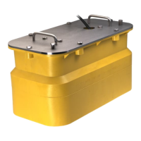
For Chirp transducers, careful consideration of temperature is important. They should be mounted in a cool, well-ventilated area, away from the engine, to prevent overheating. The liquid in the tank must not exceed 60° C (140° F) to avoid transducer failure.
The installation procedure includes establishing a performance baseline by testing the transducer's performance over the side of the boat in deep water. This baseline is then compared to the transducer's performance when temporarily placed inside the hull at the proposed mounting location. This testing can be done using various methods, such as placing the transducer directly against a clean hull with bilge water, using a thin plastic bag filled with water, or applying a water-based lubricant to ensure good acoustic coupling. This rigorous testing helps confirm the suitability of the chosen location before permanent installation.
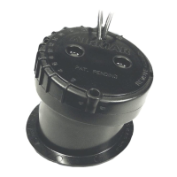
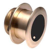
The adjustable-angle feature is central to the transducer's versatility. After measuring the hull's deadrise angle, the base of the transducer is aligned with the hull's angle using a guideline drawn perpendicular to the keel. The flange of the base has numbers representing deadrise angles, allowing for precise alignment. Once the base is securely bonded to the hull with silicone sealant, the transducer assembly is inserted into a locking ring. The locking ring features an angle indicator that aligns with ribs on the transducer, corresponding to the hull's deadrise angle, ensuring the transducer is level and its beam is directed vertically.
Proper maintenance and care are essential for the longevity and performance of the transducer. The manual provides several warnings and cautions to guide users. For instance, it explicitly states that the base must be liquid-tight, and the hull surface under and around the base must be smooth, clean, and dry to ensure a tight bond. Users are advised not to use epoxy adhesive, as it is too brittle, and to avoid solvents, cleaners, fuels, sealants, paints, and other products that may contain substances harmful to plastic parts, especially the transducer's face.
When handling the transducer, it is crucial not to pull, carry, or hold it by the cable, as this can sever internal connections. If the cable needs to be routed through bulkheads, grommets should be used to prevent chafing. To minimize electrical interference, the transducer cable should be kept separate from other electrical wiring and noise sources. Any excess cable should be coiled and secured with cable ties to prevent damage.
For installations in cored fiberglass hulls, a more involved process is required to prevent moisture penetration into the core. This involves cutting through the inner skin and core, removing the core material, sanding the inner surface of the outer skin, and filling the cavity with repair epoxy or resin before bonding the transducer base. This meticulous approach ensures the integrity of the hull and the transducer's performance.
The manual also emphasizes the importance of following the manufacturer's directions for using silicone sealant and propylene glycol, which is poured into the base after the sealant has cured to create an acoustic coupling medium. The top of the transducer must be level once the installation is complete, which is achieved by aligning the appropriate rib on the transducer with the angle indicator on the locking ring.
In case of replacement parts, the cable tag contains vital information such as the part number, date, and frequency, which should be recorded for future reference. Lost, broken, or worn parts, such as the Base & O-ring Kit (33-268-01), can be obtained from the instrument manufacturer or a marine dealer. The instructions also caution against removing the waterproof connector or cutting the cable, unless using Airmar's splash-proof Junction Box No. 33-035, as doing so will void the transducer warranty.
| Frequency | 235 kHz |
|---|---|
| Mounting | In-hull |
| Temperature Sensor | Yes |
| Power | 600 W |
| Cable Length | 10 m (33 ft) |
| Beam Width | 12° |
| Hull Angle | Up to 22° |
| Depth Rating | N/A (In-Hull) |
| Operating Temperature | -15°C to 50°C (5°F to 122°F) |