17-217-01 rev. 07 03/04
CAUTION
:
NEVER USE SOLVENTS
Cleaners, fuel, paint, sealants, and other products may
contain strong solvents, such as acetone, which attack
many plastics greatly reducing their strength.
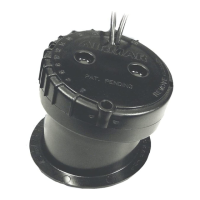
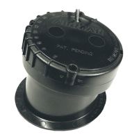
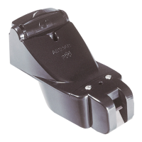
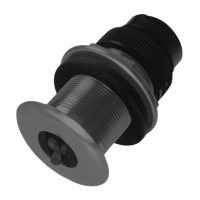
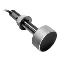
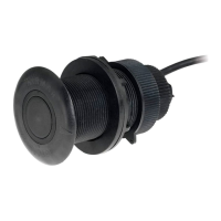
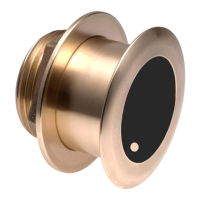
Removable In-hull Depth Transducer
Model P79
U.S. Patent No. 6,201,767 B1
EP 1 118 074 B1
Applications
• Fiberglass hulls only
• Recommended for high speed powerboats and racing sailboats
• Accommodates a deadrise angle up to 22°
Tools and Materials Needed
Adhesive tape
Pole
Detergent
Weak solvent (such as alcohol)
Safety goggles (some installations)
Dust mask (some installations)
Disk sander (some installations)
Thin sealable plastic bag (optional)
Twist-tie
Water based lubricant (K-Y® jelly) (optional)
Digital level
or
bubble level and protractor
Carpenter’s square
Pencil
Silicone sealant (such as GE Silicone
I
or Silicone
II
)
Screwdriver
Mineral oil (available at pharmacies) 71ml (2.4 fl. oz.)
For a cored fiberglass hull installation:
Drill
Hole saw 100mm
or
4"
Miniature disk sander
Casting epoxy (Polypoxy #7035/7040)
or
resin
Paper cup
Stirrer
Mounting Location
Fiberglass Hull
Since the hull absorbs acoustic energy, transmitting through the
hull reduces the sensor’s performance. Fiberglass hulls are often
reinforced in places for added strength. These cored areas
contain balsa wood or structural foam which are poor sound
conductors.
Do not locate the sensor over coring
.
Caution
: Find an area of the boat where the fiberglass is solid:
• There are no air bubbles trapped in the fiberglass resin.
• There is no coring, flotation material, or dead air space
sandwiched between the inside skin and outer skin of the hull.
Acoustic Noise
Acoustic noise is always present and these sound waves can
interfere with the operation of the transducer. Background noise
from sources such as: waves, fish, and other vessels cannot be
controlled. However, carefully selecting the transducer mounting
location can minimize the affect of vessel generated noise from
the propeller(s) and shaft(s), other machinery, and other
echosounders. The lower the noise level, the higher the
echosounder gain setting that can be used.
Placement
Choose a location where:
• The water flowing across the hull is smoothest with a minimum
of bubbles and turbulence (especially at high speeds).
• The hull below the transducer will be in contact with the water.
• The transducer beam will be unobstructed by the keel or
propeller shaft(s).
• The deadrise angle does not exceed 22
•
.
• There is adequate headroom inside the vessel for the height of
the housing, tightening the locking ring, and removing the
transducer.
Caution
: Do not mount the sensor:
Near water intake or discharge openings
Behind strakes, fittings, or hull irregularities
Behind eroding paint (an indication of turbulence)
OWNER’S GUIDE & INSTALLATION INSTRUCTIONS
Record the information found on the cable tag for future reference.
Part No._________________Date___________Frequency________kHz
IMPORTANT
: Please read the instructions completely
before proceeding with the installation. These
instructions supersede any other instructions in your
instrument manual if they differ.