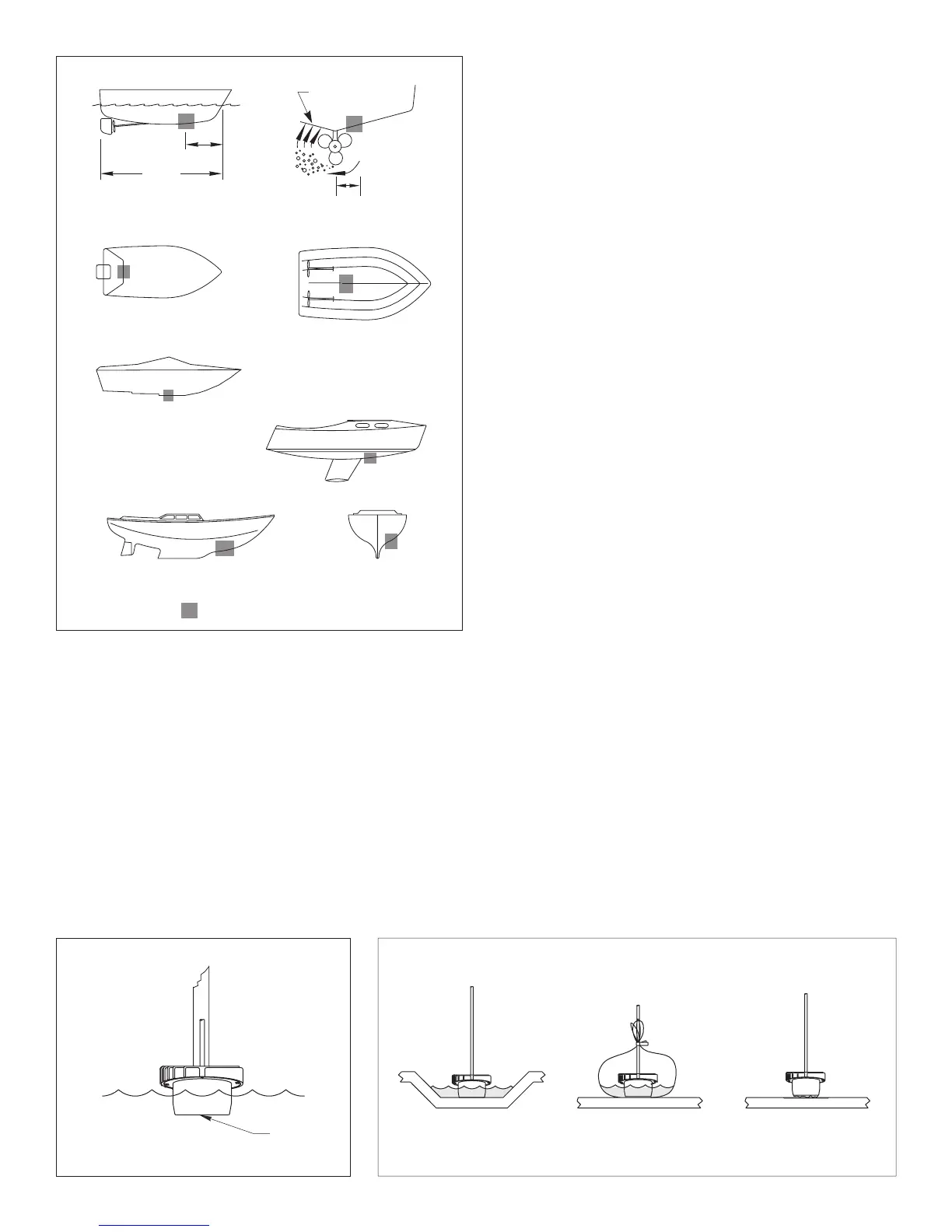
Boat Types
(see Figure 1)
•
Displacement hull powerboat
—Locate 1/3 aft LWL and
150–300mm (6–12") off the centerline on the side of the hull
where the propeller is moving downward.
•
Planing hull powerboat
—Mount well aft, on or near the
centerline, and
well inboard of the first set of lifting strakes
to
insure that the transducer is in contact with the water at high
speeds. Mount on the side of the hull where the propeller is
moving downward.
Outboard and I/O
—Mount just forward of the engine(s).
Inboard
—Mount well ahead of the propeller(s) and shaft(s).
Step-hull
—Mount just ahead of the first step.
•
Fin keel sailboat
—Mount to the side of the centerline and
forward of the fin keel 300–600mm (1–2').
•
Full keel sailboat
—Locate amidships and away from the keel
at the point of minimum deadrise angle.
Test the Selected Mounting Location
Establishing a Performance Baseline
The results of this test are used as a basis of comparison to
determine the best in-hull location for the sensor.
1. Take the boat to the maximum depth for which your instrument
is rated [up to 150m (500')] or the maximum depth in which you
will be operating the echosounder. If deep water is not available,
find a location with at least 30m (100').
2. Connect the transducer to the echosounder.
3. Tape the transducer to a pole with the cable side up. Hold it over
the side of the boat with the active face submerged in the water
(see Figure 2).
Be sure to keep the active face of the transducer
parallel to the surface of the water and fully submerged
.
4. Observe the echosounder’s performance and the depth
reading.
Testing the Mounting Location
While the boat is at the same site (depth of water), test the
transducer inside the hull at the mounting location. Use one of the
methods below:
A.This method is recommended if the sensor will be located near
the stern and the boat has a minimum deadrise angle. Clean
away any large build-up of dirt and/or grease using detergent or
a weak solvent such as alcohol. Place the transducer against
the hull and allow bilge water to cover the surface where they
touch (see Figure 3-A).
B.
Warning
: Always wear safety goggles and a dust mask.
This method can be used at any location. If the hull surface is not
smooth, grind it with a disc sander. Partially fill a thin plastic bag with
water, place the transducer inside the bag and close it tightly with a
twist-tie. Wet the surface of the hull and press the transducer’s
active face against it through the bag (see Figure 3-B).
C.
Warning
: Always wear safety goggles and a dust mask.
This method can be used at any location. If the hull surface is not
smooth, grind it with a disc sander. Coat the active face of the
transducer with a water-based lubricant (such as K-Y
®
jelly).
Press the active face against the hull with a twisting motion (see
Figure 3-C). After testing, wipe all traces of the lubricant from the
transducer’s face.
2
AIRMAR
®
inboard
Figure 1.
pressure waves
1/3 aft
full keel sailboat
displacement hull
(6-12")
fin keel sailboat
150-300mm
LWL
Best location for the transducer
(Load Waterline Length)
step-hull
planing hulls
Figure 2. Establishing a performance baseline
Figure 3. Testing the transducer at the selected location
AB C
active face
AIRMAR
®
AIRMAR
®