Observe the echosounder’s performance, and compare it to the
baseline. Look for a stable depth reading that is similar to the
baseline. If you are testing a fishfinder, compare the thickness and
intensity of the bottom trace.
If the performance is close to the baseline, this is a good mounting
location. Remember, some energy is lost transmitting through the
hull. If the test reading differs markedly from the baseline, you will
need to find another location to install the sensor.
If there is no reading or it is erratic, the transducer may be
positioned over coring which is absorbing the acoustic energy.
Choose another location. If no other spot is available,
check with
the boat manufacturer to be certain coring is present before
proceeding
with the instructions for “Installation in a Cored
Fiberglass Hull” on page 4.
Installation
1. Measure the deadrise angle of the hull at the selected location
using a digital level, or bubble level and protractor (see Figure 4).
Measure carefully, since the installed transducer must be within
5° of vertical.
Warning
: Always wear safety goggles and a dust mask.
2. The hull surface to be bonded must be smooth and free of paint
or any other finish. If the surface is rough, use a disk sander to
smooth an area 100mm (4") in diameter.
3. To ensure a tight bond, clean and dry both the selected area
and the underside of the base.Remove any dust, grease, or oil
with a weak solvent, such as alcohol.
4. Using a carpenter’s square, draw a line on the hull
perpendicular to the keel through the center of the mounting
location. This will be used as a guideline to orient the base.
5. The numbers on the flange of the base represent deadrise
angles. Identify the number that most closely corresponds to
the deadrise angle of your hull. Find its match on the opposite
side of the flange. Keeping the keel direction arrows on the side
of the base nearest the keel, align the two raised marks
indicating your deadrise angle with the guideline drawn on the
hull (see Figure 5).
Caution
: The base must be liquid-tight.
DO NOT use an epoxy adhesive, polyurethane based
sealant, or the previously recommended Boatlife® Life Seal®
or 3M™ 4200.
6. When you are satisfied that the location of the transducer is
optimal and the orientation of the base corresponds to the
deadrise angle of your boat, apply a bead of silicone sealant
(such as GE Silicone
I
or Silicone
II
) to the underside of the
flange of the base. (Follow the sealant manufacturer’s
instructions for its use.) Press the flange firmly in place to form
a liquid-tight seal. Allow the sealant to cure.
7. Slide the transducer into the locking ring. Turn the housing until
the rib that most closely corresponds to the deadrise angle of
your hull is aligned with the angle indicator on the locking ring.
To secure the housing to the locking ring, insert the two screws
(see Figure 6).
Do not
over-tighten the screws.
3
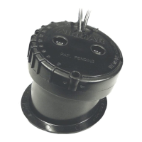
Figure 4. Deadrise angle
deadrise angle
parallel to
hull
waterline
perpendicular
to keel
base
flange
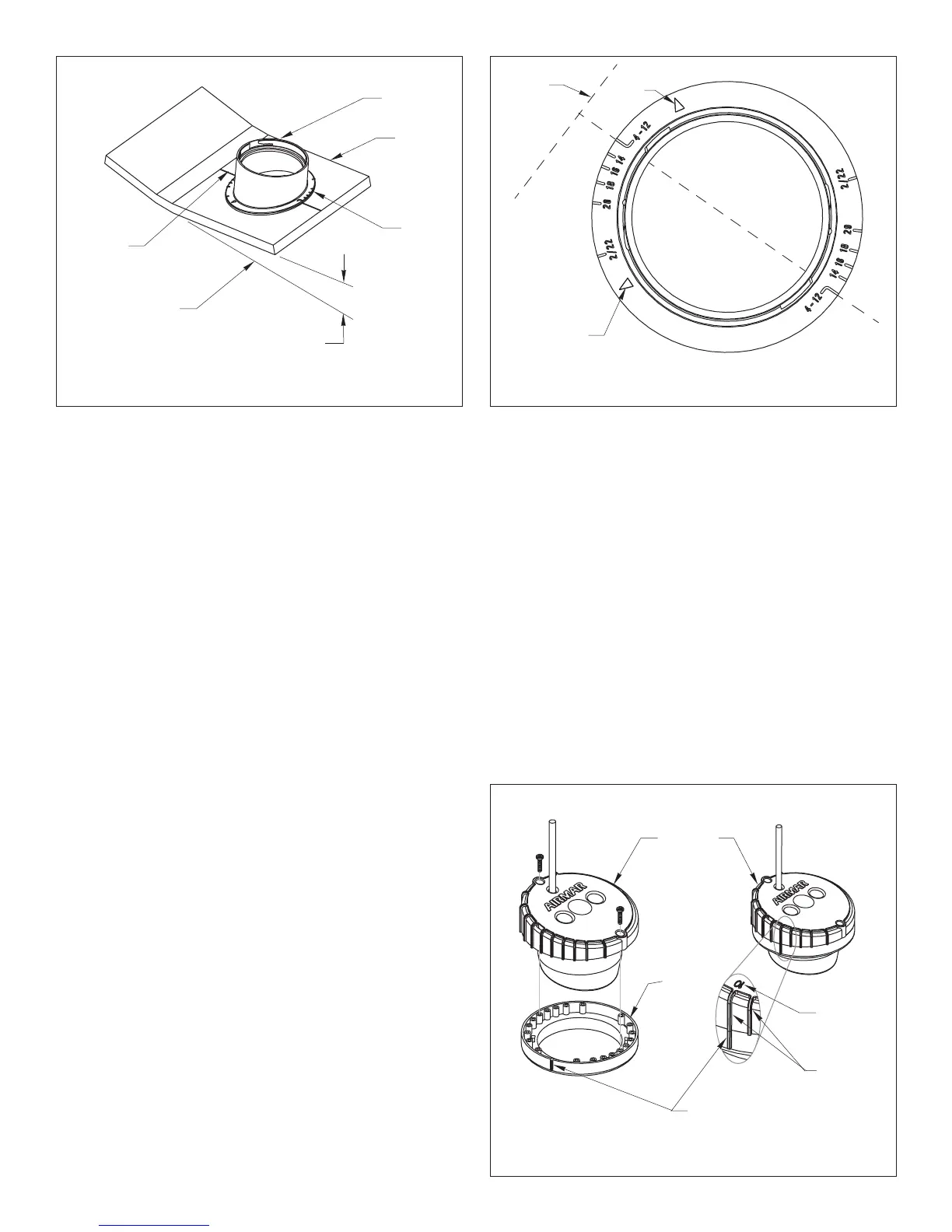
Figure 5. Aligning the flange of the base
keel direction
keel
direction
guideline
keel
arrow
arrow
(4°–12° deadrise angle shown)
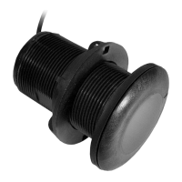
Figure 6. Joining the transducer to the locking ring
angle indicator
detail
locking
ring
transducer
ribs
10
•
deadrise
angle
shown
AIRMAR
®
AIRMAR
®
AIRMAR
®