38mm (1-1/2")
slope
of hull
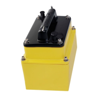
Installation
WARNING: Always wear safety goggles and a dust mask.
CAUTION: Install the bracket before attaching the sensor.
Hole Drilling
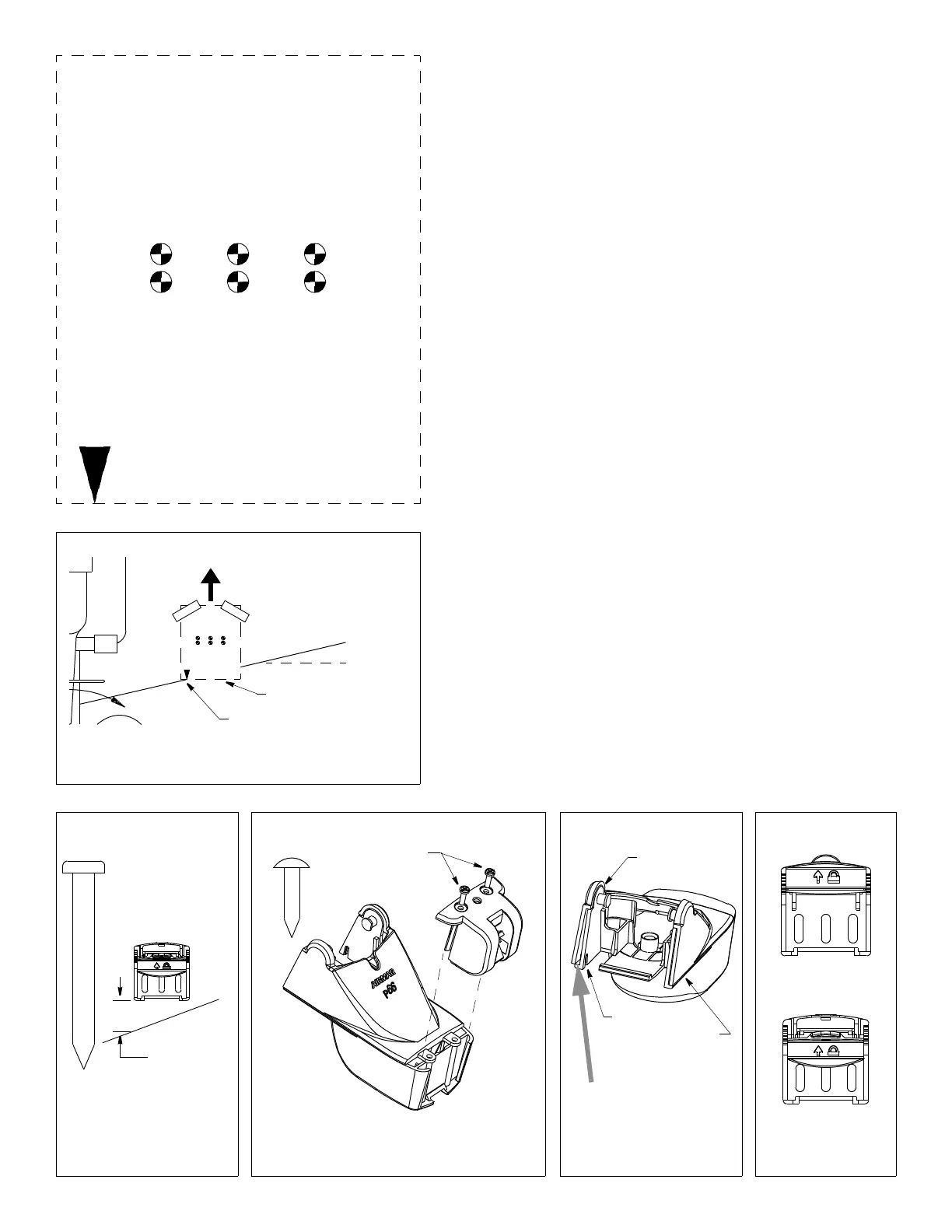
1. Cut out the template (see Figure 3).
2. At the selected location on the starboard side of the hull, position the
template, so the arrow at the bottom is aligned with the bottom edge of
the transom (see Figure 4). Being sure the template is parallel to the
waterline, tape it in place.
3. Using a 4mm, #23, or 9/64" bit, drill three holes 22mm (7/8") deep at
the locations indicated. To prevent drilling too deeply, wrap masking
tape around the bit 22mm (7/8") from the point.
Fiberglass hull—Minimize surface cracking by running the drill in
reverse until the gelcoat is penetrated.
Plastic Shim
• Standard transom (13° transom angle)—The bracket is designed for
a standard 13° transom angle. The shim is NOT needed for this
installation. Go to "Mounting the Bracket."
• Stepped transom and jet boats (3° transom angle) —Use the shim
with the taper down.
• Small aluminum and fiberglass boats (20° transom angle)—Use the
shim with the taper up.
• If you are unsure about using the shim, do one of the following:
• Measure the transom angle of your boat using an angle finder. Then
follow the instructions above for your transom angle.
• Experiment with the shim. Follow the instructions: “Mounting the
Bracket”, “Attaching the Senor to the Bracket”, and “Checking the
Angle and Projection.”
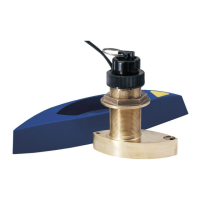
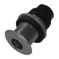
Mounting the Bracket
1. Apply marine sealant to the threads of the three, #10 x 1-3/4", self-tapping
screws to prevent water seepage into the transom (see Figure 5). Screw
the bracket (and shim if needed) to the hull. Do not tighten the screws.
2. Using the vertical adjustment space on the bracket slots, slide the bracket
up or down until the distance between the bottom left corner and the bottom
of the transom equals 38mm (1-1/2"). Tighten the screws.
Figure 4. Template position
align template arrow with
bottom edge of transom
Align template vertically
slope of hull
waterline
Align arrow with bottom of transom
Figure 3. Template
for starboard side of boat
Drill at locations labeled “B”
for transom angles 16° through 22°
(most small aluminum boats)
Drill at locations labeled “A”
for transom angles 2° through 15°
(most boats)
A
B
A
B
A
B
A
B
Figure 5. Distance between
corner of bracket and
bottom of transom
2
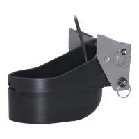
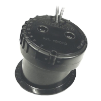
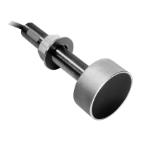
Figure 8. Bracket
retaining cover
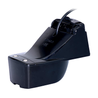
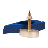
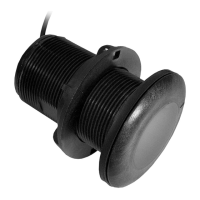
Figure 6. Speed sensor or blank
Figure 7. Cover
closed
opened
mounting ears
screws
cover
speed
sensor
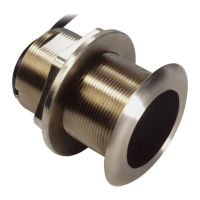
transducer
housing
(some installations)
bracket
screw
actual size
actual size
(self-tapping
#6 x 5/8")
self-tapping
screw
(some installations)
insert screw-
driver here to
remove cover
cover
tab in slot
flush with
housing
c
o
v
e
r
h
o
u
s
i
n
g
Copyright © 2003 Airmar Technology Corp.
Copyright © 2003 Airmar Technology Corp.
Copyright © 2003 Airmar Technology Corp.
Copyright © 2003 Airmar Technology
Copyright © 2003 Airmar Technology Corp.
parallel to waterline
parallel to waterline
 Loading...