EasyManua.ls Logo

Airstream TC4-2N6F - User Manual

Airstream TC4-2N6F
52 pages
Print Icon
To Next Page IconTo Next Page
Loading...
M 890-00146 rev. 07
REV. 01
TC4-2N6F

Questions and Answers

  • J
    Jill EdwardsAug 13, 2025
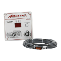
    How to fix no display on Airstream Controller?
    • M
      Martha FlemingAug 13, 2025
      If there is no display on your Airstream Controller, there are several possible causes. First, check if the circuit breaker at the service panel is off or tripped and reset it. Second, ensure that the wiring is correct. Third, verify that the voltage selector switch is in the correct position. Finally, make sure the display board interconnect cable is firmly plugged into the power supply board.
  • J
    Jerome GravesAug 16, 2025
    What to do if stage 1 or stage 2 variable speed fans are not running on Airstream Controller?
    • M
      Morgan JohnsonAug 16, 2025
      If the stage 1 or stage 2 variable speed fans are not running on your Airstream Controller, verify the wiring is correct and replace the fuse if the stage 1 or stage 2 fuse is open. Also, be sure the display board interconnect cable is firmly plugged into the power supply board. Adjust the minimum speed to a higher value, or check if the fan motor is defective by connecting it to an alternate power supply.
  • M
    Miss Kimberly YoungAug 20, 2025
    What to do if stage 3 fans are not running on Airstream Controller?
    • D
      Dylan PerezAug 20, 2025
      If the stage 3 fans are not running on your Airstream Controller, make sure the wiring is correct and replace the fuse if the stage's fuse is open. Also, be sure the display board interconnect cable is firmly plugged in. Check if the fan motor or heater is defective by connecting it to an alternate power supply. Listen to see if there is a clicking sound when the stage or heater-mist pilot light turns on, as the controller might be defective.
  • A
    Amy ThompsonAug 25, 2025
    Why stage 1 or stage 2 variable speed fans run erratically on Airstream Controller?
    • A
      Angel StoneAug 25, 2025
      If the stage 1 or stage 2 variable speed fans run erratically on your Airstream Controller, select an appropriate motor curve. If this doesn't solve the problem, adjust the band width or differential to a higher value. You may also need to adjust the stage 1 time on or time off to a higher value.
  • D
    Donna StricklandAug 28, 2025
    How to stop stage 1 fans from running continuously on Airstream Controller?
    • M
      michelle38Aug 28, 2025
      To resolve the issue of stage 1 variable speed fans running continuously when the room temperature is below the room set point on your Airstream Controller, set the stage 1 time off to a value other than zero. Also, ensure that the wiring is correct.
  • A
    Andrea SchwartzSep 1, 2025
    How to adjust mist settings on Airstream Controller?
    • K
      Kevin GonzalezSep 1, 2025
      If the mist is not operating as desired on your Airstream Controller, ensure the mist time on and time off are adjusted correctly. Also, consider that there is a 1°F(0.6°C) hysteresis on the mist and adjust the mist differential accordingly.
  • K
    kchurchSep 4, 2025
    Why does my Airstream Controller display 'P' when set to ROOM?
    • T
      Tammy TorresSep 4, 2025
      If the display shows "P" when the parameter selection knob is set to ROOM on your Airstream Controller, correct the room probe connection. For defective probes, refer to "Defective Probes".
  • L
    Lori PenningtonSep 8, 2025
    What causes temperature fluctuations on Airstream Controller display?
    • B
      Beverly HansenSep 8, 2025
      If the display shows sudden variations in the room or outside temperature on your Airstream Controller, make sure the probes are dry. Also, locate them away from drafts and sources of radiant heating to avoid electrical noise near a probe cable.

Summary

Features of the Combined Ventilation Control

Digital Display

A three-digit display for accurate temperature readings and input.

Pilot Lights Status Indicators

Lights indicating the operational status of various system outputs.

Minimum Ventilation Cycle

Operates fans continuously or intermittently to manage humidity and oxygen.

Temperature and Minimum Ventilation Speed Curves

Allows automatic adjustment of set point and minimum speed via curves.

Choice of Ten Motor Curves

Selectable motor curves for optimal compatibility and voltage supply.

Two Independent Zoned Natural Ventilation Outputs

Independently controls curtain opening for each zone based on temperature.

Outside Temperature Compensation for Natural Ventilation

Compensates curtain timer settings proportionally to the outside temperature.

Full Speed Fan Start Up

Provides 2 seconds of maximum voltage to variable speed fans at start-up.

Overload and Overvoltage Protection

Internal fuses protect circuitry from overloads and overvoltages.

Computer Control Capabilities

Enables centralized information management and diversified control via a communication module.

Precautions for Controller Installation and Operation

Controller Layout and Controls

Digital Display Overview

Displays parameters around the parameter selection knob.

Stage 1 and 2 Pilot Light

Indicates the operational status of Stage 1 and Stage 2 fans.

Curtains A Pilot Light

Indicates Zone A curtains closing or opening status.

Curtains B Pilot Light

Indicates Zone B curtains closing or opening status.

Stage 3 - 5 Pilot Light

Indicates the operational status of Stage 3 and Stage 5 fans.

Heater-Mist Pilot Light

Indicates the operational status of mist units and heaters.

Temperature Curve Pilot Light

Indicates activation of temperature and minimum speed curves.

Defective Probe Pilot Light

Illuminates when a temperature probe is detected as defective.

Locked Parameter Pilot Light

Indicates when controller parameters are locked.

Push-Button Functionality

Used to access and navigate through various adjustments.

Parameter Selection Knob

Rotary knob used to select different operational parameters.

Adjustment Knob

Rotary knob used to adjust the value of the selected parameter.

Internal Switches for Operating Modes

Installation Guide

Mounting Instructions

Guidance on securely mounting the controller enclosure to a wall.

Electrical Connections

Instructions for routing cables and making electrical connections.

Temperature Probes Setup

Details on connecting and installing room and outside temperature probes.

Extending Probe Cables

Information on how to properly extend temperature probe cables.

Installing Room Probes

Specific instructions for locating and installing room probes.

Installing the Outside Probe

Guidance on the correct placement and installation of the outside probe.

Defective Probe Identification

Procedures to identify which temperature probe is defective.

Motor Curve Selection

Instructions for selecting the appropriate motor curve for fan operation.

Operation Diagram

Using the Controller

Parameter Adjustment Ranges

Defines the adjustable range for each control parameter.

Factory Default Settings

Lists the pre-programmed settings for the controller.

Understanding Flashing Displays

Explains the meaning of flashing values on the controller display.

Temperature Unit Selection

How to set the display to show temperatures in Celsius or Fahrenheit.

Room Temperature Monitoring

How to display and interpret room temperature readings.

Minimum and Maximum Temperature Recall

Procedure to view the highest and lowest recorded room temperatures.

Resetting Minimum and Maximum Temperatures

How to clear the stored minimum and maximum temperature data.

Room Set Point and Temperature Curve Programming

Methods for setting target room temperature, including programmable curves.

Deactivating Temperature Curve

Steps to disable the programmed temperature curve.

Adjusting Room Temperature Set Point

How to manually set the desired room temperature.

Programming the Temperature Curve

Detailed steps for defining up to six points for a temperature curve.

Activating the Temperature Curve

Procedure to enable the programmed temperature curve for operation.

Displaying and Modifying Current Day Number

How to view or change the current day number on the temperature curve.

Outside Temperature Settings

Outside Temperature Display

Shows the temperature measured by the external probe.

Outside Set Point Configuration

Setting the outside temperature threshold for compensation.

Adjusting the Outside Set Point

Procedure to set or deactivate the outside temperature compensation.

Stage 1 Fan Operation and Adjustment

Minimum Ventilation Cycle Operation

How Stage 1 fans operate at minimum speed based on timer settings.

Variable Speed Ventilation

How Stage 1 fans adjust speed proportionally to room temperature.

Adjusting Stage 1 Timer Settings

Setting the ON and OFF times for the Stage 1 fan timer.

Single Minimum Speed Setting

Setting a fixed minimum speed for Stage 1 fans.

Deactivating Minimum Speed Curve

Procedure to disable the minimum speed curve for Stage 1 fans.

Adjusting Single Minimum Speed

Setting the fixed minimum speed value for Stage 1 fans.

Minimum Speed Curve Operation

Automatic adjustment of minimum speed based on a programmed curve.

Minimum Speed Curve and Temperature Curve Relation

Explains how minimum speed curves relate to temperature curves.

Minimum Speed Curve Configuration

Details on setting up the minimum speed curve points.

Specifying Minimum Speed Curve Points

Steps to define day numbers and minimum speeds for the curve.

Activating Minimum Speed Curve

Procedure to enable the minimum speed curve for Stage 1 fans.

Adjusting Stage 1 Band Width

Setting the band width parameter for Stage 1 fan speed control.

Stage 2 Fan Operation and Adjustment

Stage 2 Fan Description of Operation

How Stage 2 fans operate with increasing room temperature.

Adjusting Stage 2 Parameters

Setting minimum speed and differential for Stage 2 fans.

Stage 3 and 5 Fan Operation and Adjustment

Stage 3 and 5 Fan Description of Operation

How Stage 3 and Stage 5 fans operate based on room temperature.

Adjusting Stage 3 and 5 Differential

Setting the differential values for Stage 3 and Stage 5 fans.

Curtain Control

Curtain Operation Description

How curtains open and close based on zone temperatures and timers.

Outside Temperature Compensation for Curtains

How outside temperature affects curtain opening and closing times.

Adjusting Curtain Parameters

Setting curtain dead band and timer values.

Mist System Control

Mist Operation Description

How the mist system operates based on room temperature and timers.

Adjusting Mist Parameters

Setting mist differential and timer ON/OFF values.

Heater Control

Heater Operation Description

How heaters turn on and off based on room temperature.

Adjusting Heater Differential

Setting the ON/OFF temperature differential for heaters.

Adjusting Heater Offset

Setting the heater offset value to adjust activation temperature.

Locking Controller Parameters

Procedure to prevent accidental modification of parameter settings.

Troubleshooting Guide

No Display Troubleshooting

Solutions for when the controller display shows no output.

Display Shows P (Outside Settings)

Resolving 'P' display when setting outside temperature.

Display Shows P (Room Setting)

Resolving 'P' display when setting room temperature.

Defective Probe Pilot Light

Diagnosing issues indicated by the defective probe light.

Sudden Temperature Variations

Troubleshooting causes for fluctuating temperature readings.

Stage 1 or 2 Fans Not Running

Solutions for when variable speed fans fail to operate.

Erratic Fan Operation

Addressing issues with variable speed fans running erratically.

Continuous Fan Operation Below Set Point

Troubleshooting why Stage 1 fans run continuously below set point.

Stage 3;5 Fans or Heaters Not Operating

Solutions for Stage 3/5 fans or heaters failing to turn on.

Mist Not Operating as Desired

Resolving issues with mist system operation or settings.

Technical Specifications

Master Box Specifications

Electrical and protection specifications for the master control unit.

Slave Box No. 1 Specifications

Electrical and output specifications for Slave Box 1.

Slave Box No. 2 Specifications

Electrical and output specifications for Slave Box 2.

Slave Box No. 3 Specifications

Electrical and output specifications for Slave Box 3.

Other Component Specifications

Specifications for probes and enclosure.

Airstream TC4-2N6F Specifications

General IconGeneral
ManufacturerAirstream
TypeTemperature Controller
Outputs2 relay outputs, 6 alarm outputs
DisplayDual 4-digit LED
Power Supply100-240VAC, 50/60Hz
MountingPanel mount
InputDual RTD inputs
Control ModeOn/Off, PID
InputsThermocouple: K, J, T, E, N, S, R, B; RTD: Pt100
Enclosure RatingIP65

Related product manuals