7
Voice Processor 2x
Front and Rear Panel
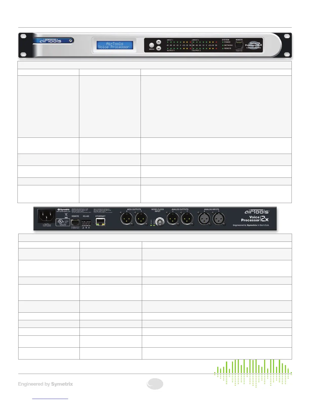
FRONT PANEL
ITEM DESCRIPTION DETAILS
MENU / UP / DOWN Momentarypushbuttons Preset Recall
1. Press MENU while on the home screen to select a channel for preset recall. Use the
UP and DOWN buttons to choose CHANNEL 1 or CHANNEL 2 for preset recall.
2. Press MENU while on CHANNEL 1 or CHANNEL 2 to select that channel for preset
recall.
3. After selecting a channel for preset recall, use the UP and DOWN buttons to scroll
through presets available for recall onto that channel.
4. Press the MENU button to recall the selected preset.
5. Press MENU again to confirm recall, or use the UP/DOWNbuttonstochoose“No”
then press MENU to cancel the recall.
System Information
• PressandHoldMENUtoenterorexittheSystemInformationMenus.
Input / Output Meters Eight(8)segmentLEDladderme-
ters, one meter of eight segments
for each input and output
Illuminatesgreenuptoandincluding0dBu,amberbetween>0andupto+23dBu,and
redtoindicateclipping(>+23dBu)oneachinputandoutput.
Power GreenLED Illuminatestoindicatethedeviceispoweredon.Note:ThepowerLEDwillflashwhilethe
device is booting.
Network
Bi-colorLED Illuminates green to indicate network (Ethernet) activity, amber to indicate acquisition of a
network address in DHCP mode.
REMOTE (LED) GreenLED Illuminates to indicate REMOTE port connection (front or rear REMOTE port).
REMOTE (Connector) RJ45 connector Distributes power and control data to a 2x Remote Control. Uses standard straight-
through UTP CAT5 cabling.
1
!
Warning! Refer to the Remote Warning for compatibility information.
REAR PANEL
ITEM DESCRIPTION DETAILS
Power Input IEC 3 prong jack Accepts power from detachable IEC power cable (100-240 VAC, 50-60 Hz, 25 Watts
max). Connect only to a grounded power outlet.
Remote RJ45 connector Distributes power and control data to a 2x Remote Control. Uses standard straight-
through UTP CAT5 cabling.
1
!
Warning! Refer to the Remote Warning for compatibility information.
RS-485 One (1) 3-pin Euroblock connector Reserved for factory use only.
Ethernet RJ45 connector Communications interface for the 2x application running on the host PC as well as 3rd
party control automation or scheduling systems. Uses standard straight-through UTP
CAT5 cabling. Features auto-crossover sensing for direct device-to-device connections.
AES3 Outputs
Two(2)MaleXLRconnectors Each software selectable to carry Channel 1/2, 1/1, 2/1 or 2/2 information. Sample rate
softwareselectablebetween44.1or48kHz,orrateofWordClockInput.
Lock GreenLED Lightssolidtoindicateavalidwordclockconnectionbetween22and192kHz.
Term GreenLED Lightssolidtoindicatesoftware-selectablewordclockinputtermination.
Word Clock Input FemaleBNCconnector AcceptsTTLorCMOS-levelwordclocksignalsfrom22to192kHz.
Analog Outputs Two(2)MaleXLRconnectors Two (2) balanced analog line level audio outputs, individually software-selectable levels of
-10dBVor+4dBu.Micleveloutputmaybesetviainternaljumpers(lineleveldefault).
Analog Inputs Two(2)FemaleXLRconnectors Two (2) balanced analog audio inputs with individually software-selectable phantom power
andlevelof-50dBu,-40dBu,-20dBu,-10dBVor+4dBu.