EasyManua.ls Logo

Airwell AWSI-HJD009-N11 User Manual

Airwell AWSI-HJD009-N11
132 pages
To Next Page IconTo Next Page
Page #1 background imageLoading...
Page #1 background image
HJD DCI Series
 – 201
REFRIGERANT
R410A
HEAT PUMP
SM HJD DCI 1-A. GB
Indoor Units Outdoor Units
AW6,-HJD009-N11 AWAU-YBDE009-H11
AW6,-HJD012-N11 AWAU-YBDE012-H11
AW6,-HJD018-N11 AWAU-YBDE018-H11
AW6,-HJD024-N11 AWAU-YBDE024-H11
ECO DESIGN
A
WSI-HJD030-N11
A
WAU-YBDE030-H11

Questions and Answers:

Airwell AWSI-HJD009-N11 Specifications

General IconGeneral
Cooling Capacity9000 BTU/h
Heating Capacity9500 BTU/h
Power Supply220-240V, 50Hz
Energy Efficiency Ratio (EER)3.21
Coefficient of Performance (COP)3.61
RefrigerantR410A
Indoor Unit Weight8 kg
TypeSplit System
Outdoor Unit Noise Level50 dB

Summary

1. Introduction to HJD DCI Series

1.1 General Overview

Overview of the HJD DCI INVERTER split wall mounted range and its models.

1.2 Main Features of HJD DCI Series

Lists the advanced technological innovations of the HJD DCI series, including DC inverter technology.

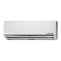
1.3 Indoor Unit Description

Describes the wall-mounted indoor unit, its design, and features.

1.4 Filtration System

Details the types of air filters available for the HJD DCI INV series.

1.5 Optional Ionizer Feature

Explains the optional ionizer feature integrated into the indoor unit.

1.6 Control System Overview

Describes the indoor controller, remote control, and networking system.

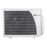
1.7 Outdoor Unit Specifications

Information on installing and features of the HJD DC INV outdoor units.

1.8 Tubing Connections Guidance

Details on flare type interconnecting tubing and where to find more information.

1.9 Available Accessories

Lists available accessories like MIU, RS485 Adapter, Base Heater, M2L cable Port.

1.10 Included Documentation

Information about the documentation supplied with each unit.

1.11 Unit Matching Table

Provides a table showing compatibility between outdoor and indoor units.

1.11.1 R410A Refrigerant Matching

Specific matching table for R410A refrigerant.

2. Product Data Sheets for HJD DCI Series

2.1 HJD009 DCI Specifications

Detailed specifications for the HJD009 DCI model, including indoor and outdoor unit data.

2.2 HJD012 DCI Specifications

Detailed specifications for the HJD012 DCI model, including indoor and outdoor unit data.

2.3 HJD018 DCI Specifications

Detailed specifications for the HJD018 DCI model, including indoor and outdoor unit data.

2.4 HJD024 DCI Specifications

Detailed specifications for the HJD024 DCI model, including indoor and outdoor unit data.

2.5 HJD030 DCI Specifications

Detailed specifications for the HJD030 DCI model, including indoor and outdoor unit data.

3. Rating Conditions and Operating Limits

3.1 Operating Limits

Defines the operating limits for cooling and heating modes.

3.1.1 R410A Refrigerant Limits

Specifies operating limits for R410A refrigerant.

4. Outline Dimensions of HJD DCI Units

4.1 Indoor Unit Dimensions: HJD009 / 012 DCI

Provides dimensions for indoor units HJD009 and HJD012.

4.2 Outdoor Unit Dimensions: YBDE009 / 012

Provides dimensions for outdoor units YBDE009 and YBDE012.

4.3 Indoor Unit Dimensions: HJD018 / 024

Provides dimensions for indoor units HJD018 and HJD024.

4.4 Outdoor Unit Dimensions: YBDE018 / 024

Provides dimensions for outdoor units YBDE018 and YBDE024.

4.5 Indoor Unit Dimensions: HJD030

Provides dimensions for indoor unit HJD030.

4.6 Outdoor Unit Dimensions: YBDE030

Provides dimensions for outdoor unit YBDE030.

5. Performance Data and Pressure Curves

5.1 HJD009 / YBDE009 DCI Performance

Cooling capacity data and capacity correction factors for HJD009/YBDE009.

5.1.3 Heating Capacity and Correction Factors

Heating capacity data and correction factors for HJD009/YBDE009.

5.2 Tubing Length Capacity Correction

How tubing length affects cooling and heating capacity.

5.3 HJD012 / YBDE012 DCI Performance

Cooling capacity data and correction factors for HJD012/YBDE012.

5.3.3 Heating Capacity and Correction Factors

Heating capacity data and correction factors for HJD012/YBDE012.

5.4 Tubing Length Capacity Correction

How tubing length affects cooling and heating capacity.

5.5 HJD018 / YBDE018 Performance

Cooling capacity data and correction factors for HJD018/YBDE018.

5.5.3 Heating Capacity and Correction Factors

Heating capacity data and correction factors for HJD018/YBDE018.

5.6 HJD024 / YBDE024 Performance

Cooling capacity data and correction factors for HJD024/YBDE024.

5.6.3 Heating Capacity and Correction Factors

Heating capacity data and correction factors for HJD024/YBDE024.

5.7 HJD030 / YBDE030 Performance

Cooling capacity data and correction factors for HJD030/YBDE030.

5.7.3 Heating Capacity and Correction Factors

Heating capacity data and correction factors for HJD030/YBDE030.

5.8 Tubing Length Capacity Correction

How tubing length affects cooling and heating capacity.

5.9 Pressure Curves (Cooling Test Mode)

Pressure curves for HJD009/YBDE009 DCI cooling test mode.

5.9.2 Heating Pressure Curves (Test Mode)

Pressure curves for HJD009/YBDE009 DCI heating test mode.

5.9.3 HJD012/YBDE012 DCI Cooling Pressure Curves

Pressure curves for HJD012/YBDE012 DCI cooling test mode.

5.9.4 HJD012/YBDE012 DCI Heating Pressure Curves

Pressure curves for HJD012/YBDE012 DCI heating test mode.

5.9.5 HJD018/YBDE018 DCI Cooling Pressure Curves

Pressure curves for HJD018/YBDE018 DCI cooling test mode.

5.9.6 HJD018/YBDE018 DCI Heating Pressure Curves

Pressure curves for HJD018/YBDE018 DCI heating test mode.

5.9.7 HJD024/YBDE024 DCI Cooling Pressure Curves

Pressure curves for HJD024/YBDE024 DCI cooling test mode.

5.9.8 HJD024/YBDE024 DCI Heating Pressure Curves

Pressure curves for HJD024/YBDE024 DCI heating test mode.

5.9.9 HJD030/YBDE030 DCI Cooling Pressure Curves

Pressure curves for HJD030/YBDE030 DCI cooling test mode.

5.9.10 HJD030/YBDE030 DCI Heating Pressure Curves

Pressure curves for HJD030/YBDE030 DCI heating test mode.

6. Sound Level Characteristics

6.1.1 Indoor Units Test Scheme

Describes the test setup for measuring indoor unit sound levels.

6.1.2 Indoor Sound Pressure Level Spectrum

Presents the sound pressure level spectrum and NC curves for HJD030.

6.2 Outdoor Units Overview

General information about outdoor units.

6.2.1 Outdoor Sound Pressure Level Spectrum

Sound pressure level spectrum and NC curves for outdoor units.

7. Electrical Data for HJD DCI Series

7.1 Single Phase Unit Electrical Specs

Electrical specifications for single-phase units, including current and wiring.

8. Wiring Diagrams

8.1 HJD 009/012 Indoor & YBDE 009/012 Outdoor Units

Wiring diagrams for HJD009/012 indoor and YBDE009/012 outdoor units.

8.2 HJD 018 Indoor Unit Wiring

Wiring diagram for the HJD018 indoor unit.

8.3 YBDE018 Outdoor Unit Wiring

Wiring diagram for the YBDE018 outdoor unit.

8.4 HJD024 DCI Indoor Unit Wiring

Wiring diagram for the HJD024 DCI indoor unit.

8.5 YBDE024 Outdoor Unit Wiring

Wiring diagram for the YBDE024 outdoor unit.

8.6 HJD030 DCI Indoor Unit Wiring

Wiring diagram for the HJD030 DCI indoor unit.

8.7 YBDE030 DCI Outdoor Unit Wiring

Wiring diagram for the YBDE030 DCI outdoor unit.

9. Tubing Connections

Tubing Specifications and Torque Values

Details on tube size, torque, and components for connections.

10. Refrigeration Diagrams

10.1 Heat Pump Models Diagram

Refrigeration circuit diagram for heat pump models.

11. Electrical Connections

11.1 HJD009, 012, 018 DCI Connections

Electrical connection diagrams for HJD009, 012, 018 DCI models.

11.2 HJD030 DCI Connections

Electrical connection diagram for the HJD030 DCI model.

12. Control System

12.1 Control System Abbreviations

Glossary of abbreviations used in the control system section.

12.2 Product Overview and Controllers

General overview of the control system, including block diagrams and controller types.

12.2.2 Main Controller Details

Details of the main controllers for outdoor and indoor units.

12.2.3 Control Features Explained

Explanation of various control features like compressor, fan, and valve control.

12.2.3.3 Outdoor Fan Control

Describes the operation of outdoor fans, including DC brushless and AC track motors.

12.2.3.4 Reverse Valve (RV) Function

Explanation of Reverse Valve function in cooling and heating modes.

12.2.3.5 Electronic Expansion Valve (EEV)

Details on Electronic Expansion Valve operation.

12.2.3.6 Human Machine Interface (HMI)

Description of the Human Machine Interface (HMI) features.

12.2.3.7 Dry Contact Functionality

Explanation of dry contact functions and their applications.

12.2.3.7.1 YBDE 030 ODU Dry Contacts

Specific dry contact features for YBDE030, including Night, SB, Forced Mode, and Alarm.

12.2.3.7.2 YBDE 018/024 ODU Dry Contacts

Specific dry contact features for YBDE018/024, including Alarm output behavior.

12.2.3.7.3 IDU Dry Contacts

Dry contacts for indoor units, including Clock/Presence detector.

12.2.3.8 Temperature Sensor Mapping

Table mapping sensor actions to temperature readings and system reactions.

12.2.3.9 Base Heater Operation

Information on the base heater operation and its relation to RV and OAT.

12.3 System Configuration Tests

Details on system configuration tests, including auto detection.

12.3.3.1 Communication Channel Auto Detection

Procedure for automatic detection of communication channels in single or multi systems.

12.3.3.2 Model Plug & Indoor Capacity Test

Tests for model compatibility and indoor capacity group configuration.

12.3.4 Thermistor Measurements

Default values and system reactions for various thermistors.

12.3.4.2 Thermistor Fault Detection

Lists thermistor faults and their corresponding temperature conditions.

12.3.4.3 Thermistor Fault Operation

Describes system behavior and responses when thermistor faults are detected.

12.4 Indoor Unit Control Logic

Details on indoor unit control logic, including load calculation.

12.4.1 Load Calculation Explained

Explains how the LOAD is calculated based on room temperature and set point.

12.4.2 Indoor Fan Control

How indoor fan speed is controlled in different modes.

12.4.2.1 FAN Mode Fan Control

FAN mode operation based on user setting and calculated LOAD.

12.4.2.2 Cool Mode Fan Control

Indoor fan control logic during Cool Mode.

12.4.2.3 Heat Mode Fan Control

Indoor fan control logic during Heat Mode.

12.4.2.3.1 IFAN Operation in Set Speed

IFAN operation based on set speed and conditions.

12.4.2.3.2 IFAN Operation in Auto Fan Mode

IFAN operation in Auto Fan Mode based on Load.

12.4.3 Cooling Mode Operations

Details on Cooling Mode operation.

12.4.3.1 Cooling Mode - General

General definition of Cooling Mode, including settings and detected parameters.

12.4.3.2 Cooling Mode Control Functions

Control functions within Cooling Mode, covering COMP, OFAN, IFAN, RV, Heaters, Pump.

12.4.3.3 Cooling Mode Sequence Diagrams

Sequence diagrams illustrating room temperature control in Cooling Mode.

12.4.4 Heating Mode Operations

Details on Heating Mode operation.

12.4.4.1 Heating Mode - General

General definition of Heating Mode, including settings and detected parameters.

12.4.4.2 Heating Mode Control Functions

Control functions within Heating Mode, covering COMP, OFAN, IFAN, RV, Heaters, Pump.

12.4.4.3 Heating Mode Sequence Diagram

Sequence diagram illustrating room temperature control in Heating Mode.

12.4.4.4 Temperature Compensation in Heating

Explanation of temperature compensation in I-Feel mode for heating.

12.4.4.5 Indoor Fan Control in Heat Mode

Indoor fan control logic specifically for Heat Mode.

12.4.5 Automatic Cooling or Heating

Details on automatic mode switching between cooling and heating.

12.4.5.1 Automatic Mode - General

General definition and parameters for automatic mode.

12.4.5.2 Automatic Mode Control Functions

Control functions for automatic mode, including temperature switching and mode changes.

12.4.5.3 Automatic Mode Change Table

Table showing time taken for mode changes between Auto Cool and Auto Heat.

12.4.6 Dry Mode Operations

Details on Dry Mode operation.

12.4.6.1 Dry Mode - General

General definition of Dry Mode, including settings and control functions.

12.4.6.2 Dry Mode Control Functions

Control functions specific to Dry Mode (COMP, OFAN, IFAN, RV, HEATERS, Pump).

12.4.6.3 Dry Mode Sequence Diagrams

Sequence diagrams for reducing humidity in Cool Mode with low IFAN speed.

12.4.7 Sleep Mode Operations

Details on Sleep Mode operation and control functions.

12.4.7.1 Sleep Mode - General

General definition of Sleep Mode, including settings and control functions.

12.4.7.2 Sleep Mode Control Function

Control functions within Sleep Mode, including SPT adjustment and TIMER function.

12.4.7.3 Sleep Mode Sequence Diagrams

Sequence diagrams illustrating Sleep Mode operation.

12.4.8 Forced Operation Mode

How to set and operate the unit in Forced Operation mode.

12.4.9 Indoor Unit Mode vs. Outdoor Unit Mode

Behavior when indoor and outdoor unit modes are different.

12.4.10 Indoor Unit Dry Contact Functions

Functionality of indoor unit dry contacts for clock and presence detection.

12.4.11 Ducted Indoor Unit Controls & Indicators

Explanation of controls and indicators on ducted indoor units.

12.4.1 LCD Display Controls & Indicators

Controls and indicators for HJD009/012/018/024 indoor units with LCD display.

12.4.2 HJD 030 LCD Display Controls & Indicators

Controls and indicators for the HJD030 indoor unit with LCD display.

12.4.3 Outdoor Unit Controls and Indicators

Controls and indicators for outdoor units.

12.4.3.1 7-Segment Display Description

Description of the 7-segment display on the user interface.

12.4.3.2 User Interface Menu Concept

Explanation of the user interface concept using tree menus.

12.4.3.3 Menu Navigation

How to navigate menus using keypad or remote controller.

12.8.3 Menu Navigation Structure

Overview of the menu structure.

12.8.3.1 Main Menu Options

The main menu structure and options available.

12.8.3.2 Status Sub-Menu

Status sub-menu for viewing unit information.

12.9 Jumper/DIP-Switch Settings

Configuration settings using jumpers and DIP switches.

12.9.1 Jumper/DIP-Switch Definitions

Definitions for jumper/DIP switch settings.

12.9.2 IDU Jumper/DIP Settings

Specific jumper/DIP switch settings for Indoor Units.

12.9.2.1 Self-Test Jumper/DIP (J1)

Jumper/DIP setting for self-test function.

12.9.2.2 Compensation Jumper/DIP (J2)

Jumper/DIP setting for compensation function.

12.9.2.3 Family Selection Jumper/DIP

Jumper/DIP settings for family selection.

12.9.2.4 Model Selection Jumper/DIP (J7, J8)

Jumper/DIP settings for model selection.

12.9.2.5 Presence Detector Jumper/DIP (J9)

Jumper/DIP setting for presence detector.

12.9.3 ODU Jumper Settings

Jumper settings for Outdoor Units.

12.9.3.1 ODU Self-Test Jumper/DIP (J1)

Jumper/DIP setting for self-test on ODU.

12.9.3.2 ODU Model Selection Jumper/DIP

Jumper/DIP settings for ODU model selection.

12.9.4 Dip-Switch Setting Table

Table showing DIP switch settings for various models.

12.9.5 Remote Control DIP Switch Settings

DIP switch settings for the remote control.

12.10 System Parameters Overview

General system parameters for all models.

12.10.1 General Parameters Table

Table of general system parameters with default values.

12.10.2 ODU Model Dependent Parameters

System parameters that vary based on the Outdoor Unit model.

12.10.3 IDU Model Dependent Parameters

System parameters that vary based on the Indoor Unit model.

12.11 7-Segment Display Legend

Legend for interpreting characters displayed on the 7-segment display.

13. Troubleshooting Guide

13.1 Precautions and Notices

Important safety precautions and notices for troubleshooting.

13.1.1 High Voltage Safety

Warning about high voltage in electrical assemblies and safety measures.

13.1.2 Charged Capacitor Safety

Warning about charged capacitors and safety precautions.

13.2 General System Failures and Corrective Actions

Common system failures and their corresponding corrective actions for indoor units.

13.2 Continued: Outdoor Unit Failures

Corrective actions for outdoor unit failures and compressor issues.

13.2 Continued: Heating and Operational Issues

Troubleshooting for heating capacity issues, compressor overheating, and operational problems.

13.2 Continued: EMC and Other Issues

Troubleshooting for freezing, operational interruptions, and EMC issues.

13.3 Refrigeration System Checks

Procedures for checking refrigeration system pressures and thermodynamic measures.

13.4 Troubleshooting by Diagnostics Codes

Guide to interpreting diagnostic codes for troubleshooting.

13.4.1 Outdoor Unit Fault Codes

Table of fault codes for outdoor units and their possible causes/actions.

13.4.2 Outdoor Unit Diagnostics and Actions

Diagnostic codes and corrective actions for outdoor unit issues.

13.4.2 Continued: Outdoor Unit Actions

Corrective actions for various outdoor unit faults, including protection and operational issues.

13.4.3 Indoor Unit Fault Codes

How to view indoor unit fault codes via the indoor unit LED display.

13.4.4 Indoor Unit Diagnostics and Actions

Table of indoor unit faults, probable causes, and corrective actions.

13.4.4 Continued: Indoor Unit Actions

Corrective actions for outdoor unit protection, indoor coil protection, overflow, EEPROM, and communication issues.

13.5 Main Parts Checking Procedures

Procedures for checking main components of the unit.

13.5.1 High Voltage DC Check

Safety warning and procedure for checking DC voltage.

13.5.2 Mains Voltage Check

Procedure for checking mains voltage and related issues.

13.5.3 Line Filter Check

Steps to check the line filter for damage or output voltage.

13.5.4 Compressor Driver Check

Troubleshooting steps for compressor driver issues in YBD018-024 and YBD030 models.

13.5.5 PFC Chock Coil Check

Procedure for checking the PFC chock coil and its connections.

13.5.6 Outdoor Fan Motor Check

Steps to check the outdoor fan motor, voltage, and sensor readings.

13.5.7 Compressor Check

How to check compressor resistance and current.

13.5.8 Reverse Valve (RV) Check

Procedure for checking the RV connector, voltage, and operation.

13.5.9 Electrical Expansion Valve (EEV) Check

Information on checking the EEV parts, step motor, and coil.

13.5.10 Thermistor Checks

Steps to check thermistor connections, wiring, visual condition, and resistance.

13.5.11 Indoor-Outdoor Unit Communications Check

Procedure for checking interconnection wiring voltage and connections.

13.5.12 Indoor Unit Fuse Check

Troubleshooting steps for a burnt 3.15A fuse on the main board.

13.5.13 High Pressure Switch (HPS) Check

Procedure for checking HPS connector and resistance.

13.5.14 Indoor Unit Fan Motor Check

Steps to check the indoor fan motor, capacitor, and coil resistance.

13.5.15 EMC Interference Checks

Identifying locations susceptible to EMC and corrective actions.

13.5.15.1 EMC Interference to A/C Unit

Specifics on EMC interference affecting the A/C unit.

13.5.15.2 EMC Interference to Home Appliances

Specifics on EMC interference affecting home appliances.

14. Exploded Views and Spare Part Lists

14.1 Exploded View: HJD009/012 DCI Indoor Unit

Exploded view diagram for HJD009/012 DCI indoor units.

14.2 Spare Parts: HJD009 DCI Indoor Unit

Spare parts list for HJD009 DCI indoor units with item numbers and descriptions.

14.3 Spare Parts: HJD018 DCI Indoor Unit

Spare parts list for HJD018 DCI indoor units with item numbers and descriptions.

14.4 Exploded View: HJD024 DCI Indoor Unit

Exploded view diagram for HJD024 DCI indoor units.

14.5 Spare Parts: HJD024 DCI Indoor Unit

Spare parts list for HJD024 DCI indoor units with item numbers and descriptions.

14.6 Exploded View: HJD030 DCI Indoor Unit

Exploded view diagram for HJD030 DCI indoor units.

14.7 Spare Parts: HJD030 DCI Indoor Unit

Spare parts list for HJD030 DCI indoor units with item numbers and descriptions.

14.8 Exploded View: YBDE009/012 DCI Outdoor Unit

Exploded view diagram for YBDE009/012 DCI outdoor units.

14.9 Exploded View: YBDE018-H11 Outdoor Unit

Exploded view diagram for YBDE018-H11 outdoor units.

14.12.2 Outdoor Unit Parts Assembly

Detailed parts assembly diagrams for outdoor units.

14.13 Spare Parts: YBDE 018-H11 Outdoor Unit

Spare parts list for YBDE 018-H11 outdoor units.

14.13.1 Exploded View: YBDE 024-H11 Outdoor Unit

General assembly exploded view for YBDE 024-H11 outdoor unit.

14.13.2 Outdoor Unit Parts Assembly

Detailed parts assembly diagrams for YBDE 024-H11 outdoor unit.

14.13.3 Spare Parts: YBDE 024-H11 Outdoor Unit

Spare parts list for YBDE 024-H11 outdoor units.

14.14 Exploded View: OU8DCI Outdoor Unit

Exploded view diagram for OU8DCI outdoor units.

14.14.2 Outdoor Unit Parts Assembly

Detailed parts assembly diagrams for OU8DCI outdoor units.

14.14.3 Spare Parts: YBDE012 DCI Outdoor Unit

Spare parts list for YBDE012 DCI outdoor units.

14.14.1 General Assembly: OU8DCI Outdoor Unit

General assembly exploded view for OU8DCI outdoor units.

14.14.2 OU8DCI Outdoor Unit Parts Assembly

Detailed parts assembly diagrams for OU8DCI outdoor units.

14.14.4 Spare Parts: YBDE012 DCI Outdoor Unit

Spare parts list for YBDE012 DCI outdoor units.

14.14.1 Spare Parts: OU0831DCA Outdoor Unit

Spare parts list for OU0831DCA outdoor units.

14.14.2 Spare Parts: OU0830DCA Outdoor Unit

Spare parts list for OU0830DCA outdoor units.

14.14.3 Spare Parts: ELCO INV35 / OU0830DCA

Spare parts list for ELCO INV35 / OU0830DCA outdoor units.

14.14.4 Spare Parts: AWAU-YBDE030-H11 Outdoor Unit

Spare parts list for AWAU-YBDE030-H11 outdoor units.

APPENDIX A

Related product manuals