Page 27
English
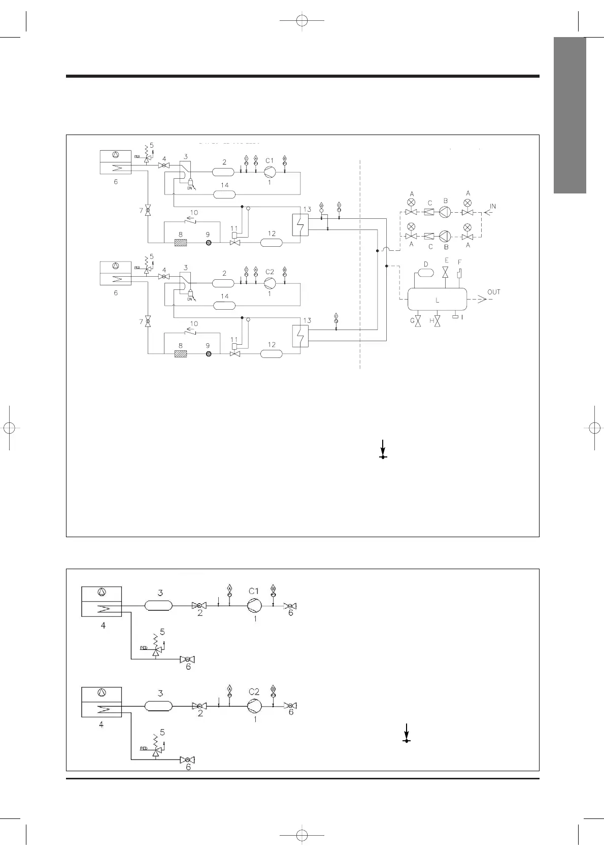
General Description
Components of the hydraulic plant
(optional):
A Shut-off valve
B Pump(s)
C Nonreturn valve
D Expansion valve
E Plant discharge safety valve
F Air vent
G Filling valve
H Discharge valve
I Pressure gauge
L Storage tank
Components of the refrigeration
system:
1 Compressors C1 / C2
2 Silencer (ELN only)
3 Reversing valve
4 Delivery cock
5 PED safety valve
6 Coil
7 Liquid cock
8 Filter
9 Liquid sight glass
10 Check valve
11 Thermostatic valve
12 Liquid receiver
13 Plate-type heat exchanger
14 Liquid separator
Safety devices:
A HP pressure switch
B LP pressure switch
C Transducer
D Water differential pressure switch
Pressure and charge/discharge inlets
Freon
CLH refrigeration diagram
CLC refrigeration diagram
Components of the refrigeration
system:
1 Compressors C1 / C2
2 Delivery cock
3 Silencer (only ELN)
4 Coil
5 Ped Safety Valve
6 Liquid cock
Safety devices:
A HP Pressure switch
B LP Pressure switch
Pressure and charge/discharge
inlets freon
REFRIGERATION PLANT
HYDRAULIC PLANT (OPTIONAL)
REFRIGERATION PLANT
 Loading...