EasyManua.ls Logo

Airwell Itelco-Clima CLS 182 STD User Manual

Airwell Itelco-Clima CLS 182 STD
83 pages
To Next Page IconTo Next Page
Page #1 background imageLoading...
Page #1 background image
English
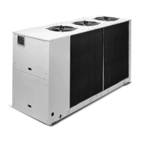
Air cooled water chillers, air cooled condensing units and air-to-water
reverse cycle heat pumps
Installation and maintenance manual
IOM CLSCH-N.1GB
Date : November 2005
Supersedes : None
CLS/CLC/CLH
182 ÷ 602
41
140 kW
46
152 kW
Библиотека СОК

Table of Contents

Questions and Answers:

Airwell Itelco-Clima CLS 182 STD Specifications

General IconGeneral
BrandAirwell
ModelItelco-Clima CLS 182 STD
CategoryChiller
LanguageEnglish

Summary

Installation and Maintenance Manual

1 FOREWORD

1.2 Warranty Terms

Details warranty conditions and coverage for the unit.

2 SAFETY

2.1 Safety Compliance

States compliance with directives and general safety advice.

2.4 Residual Risk Prevention

Details precautions for control, mechanical, and electrical residual risks.

2.5 Maintenance Safety

Lists safety measures for maintenance operations.

3 TRANSPORT, LIFTING AND POSITIONING

3.2 Lifting Procedures

Details safe lifting methods and precautions.

4 INSTALLATION

4.1 Unit Positioning Guidelines

Covers placement and environmental considerations for the unit.

4.3 External Hydraulic Circuit Requirements

Details components and requirements for the external hydraulic system.

4.6 Power Supply Requirements

Outlines general power supply and grounding requirements.

4.7 Electrical Connections

Details electrical connection standards and precautions.

5 START-UP

5.1 Preliminary Checks

Lists pre-start checks for the unit and plant.

5.2 Start-up Sequence

Details the step-by-step procedure for starting the unit.

5.3 Checking Operation Parameters

Lists parameters to check after start-up.

6 CONTROL

6.1 General Information on Control System

Overview of the electronic control system and its functions.

6.2 Control System Details

Explains temperature regulation and antifreeze functions.

6.4 Unit Start-up Procedures

Details start-up for different unit models.

6.6 Main Alarms and Reset

Lists main alarms, their causes, and reset procedures.

7 GENERAL DESCRIPTION

7.8 Electrical Power Supply and Control System

Describes the control compartment and its components.

8 TECHNICAL DATA

8.2 Technical Data: CLS STD and CLC STD

Specs for CLS/CLC STD models (182-352).

8.2 Technical Data: CLS STD and CLC STD (cont.)

Continues specs for CLS/CLC STD models (402-602).

8.2 Technical Data: CLS LN and CLC LN

Specs for CLS/CLC LN models (182-352).

8.2 Technical Data: CLS LN and CLC LN (cont.)

Continues specs for CLS/CLC LN models (402-602).

8.2 Technical Data: CLS ELN and CLC ELN

Specs for CLS/CLC ELN models (182-352).

8.3 Unit Electrical Data: CLS/CLC STD

Electrical data for CLS/CLC STD models.

8.3 Unit Electrical Data: CLS/CLC LN-ELN

Electrical data for CLS/CLC LN-ELN models.

8.3 Unit Electrical Data: CLS/CLC HT-HPF

Electrical data for CLS/CLC HT-HPF models.

8.3 Unit Electrical Data: Compressors and Pumps

Detailed electrical data for compressors and pumps.

8.3 Unit Electrical Data: CLH STD

Electrical data for CLH STD models.

8.3 Unit Electrical Data: CLH LN

Electrical data for CLH LN models.

8.3 Unit Electrical Data: CLH HPF

Electrical data for CLH HPF models.

8.3 Unit Electrical Data: Compressors CLH

Electrical data for CLH compressors and pumps.

9 MAINTENANCE

9.2 Planned Maintenance Schedule

Details daily, weekly, and monthly maintenance tasks.

9.3 Refrigerant Charge Procedures

Instructions for proper refrigerant charging and precautions.

10 TROUBLESHOOTING

Common Anomalies and Causes

Lists common unit anomalies, their causes, and solutions.

Compressor and Line Issues Troubleshooting

Covers issues like non-working compressors and hot/frosted liquid lines.

Related product manuals