15
ICE CFA1120A-3360A & CGA3180A I&O Manual 03/2021 Rev.5
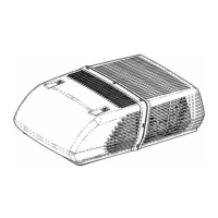
Output Termination for Indoor Motor Control Signal
Note: Follow data (wiring and signal control signal type) of the appropriate motor to setup the PCB
1 2
1
Indoor Motor PWM Signal Output. Reference Wire Connected to “GND” and
the Signal Connected to “PWM”
2
3
Indoor Motor 0-10V Signal Output. Reference Wire Connected to “GND” and
the Signal Connected to “0-10V”
4
Figure 3. Output Termination for Indoor Motor Control Signal
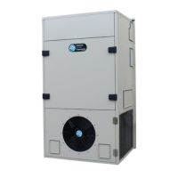
Setting the Speed for Outdoor Motor
The Outdoor Motor runs at constant speed dictated by the potentiometer. See gure below.
3
1
2
1 Set for 0-10V Signal. Jumper To Remain On The Appropriate Terminal For Correct Operation
2 Set For PWM Signal. Jumper To Remain On The Appropriate Terminal For Correct Operation
3 Outdoor Motor Speed Potentiometer
Figure 4. Outdoor Motor Speed Setting
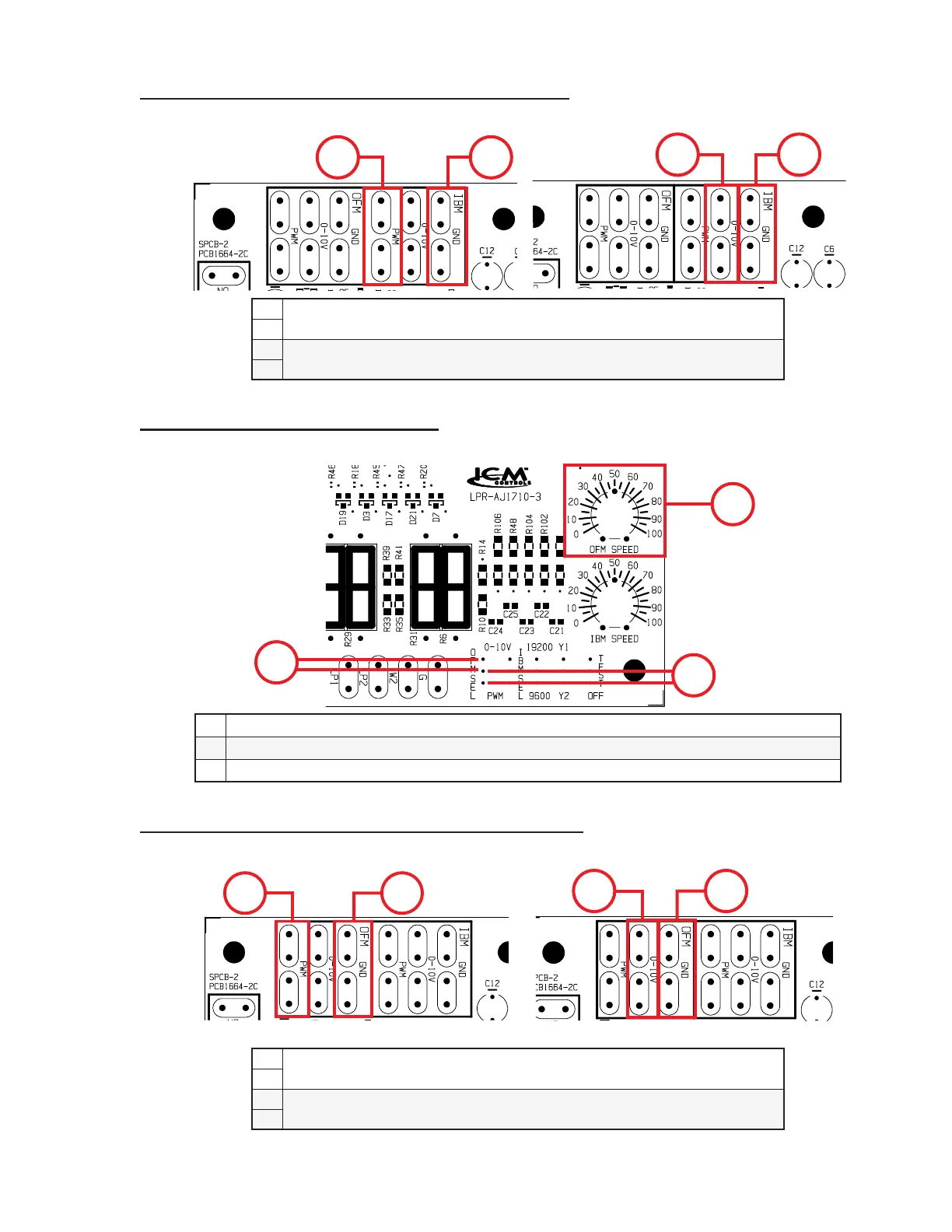
Output Termination for Outdoor Motor Control Signal
Note: Follow data (wiring and signal control signal type) of the appropriate motor to setup the PCB.
1 2
3
4
Note that there are redundant (2 of each) output signal terminations for each motor.
1
Outdoor Motor PWM Signal Output. One Wire Connected to “GND” and the
Other Connected to “PWM”
2
3
Outdoor Motor 0-10V Signal Output. One Wire Connected to “GND” and the
Other Connected to “0-10V”
4
Figure 5. Output Termination for Outdoor Motor Control Signal
 Loading...