6
A-MIP 200 V1.06
Installation
• Use suitable mounting method for the type of
substrate on which Aivia is installed.
• Mounting must be able to support a minimum load of
20 Kg.
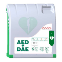
• Mounting example:
• The screw head washer set must not exceed 8mm
thick.
Use the 3 mounting holes to mount the Aivia.
Connect power to the Aivia
The Aivia must be supplied with 24VDC power,
ensure compliance with the "Electrical Installation"
section
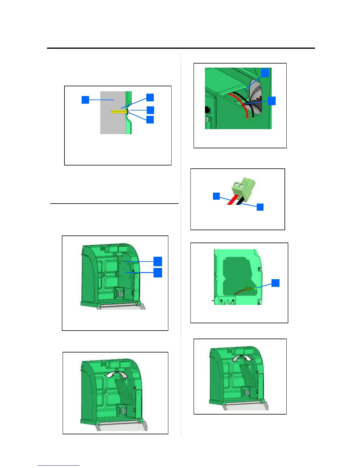
• Unscrew the door mounting screw with a star
screwdriver and tip the door from above.
• Pass power wiring through the wiring pass through
• Connect cables to the supply terminals, respecting
proper polarity.
• Connect the terminal to the power connector.
Ensure that the Aivia is under power by checking that
the red warning lights are blinking.
Replace the access door by insert the lower edge
first.
• Insert mounting screws using a start screwdriver.
1
2
3
4
1 Supporting wall.
2 Pin/Nylon plug.
3 Fixing screw, M6 minimum, M8 maximum.
4 Shim 14mm maximum.
1
2
1
2
2
1
1
2
2
1
1
2
1
Access door mounting screws.
Electronics access door
1 Power connection
Seal openings.
Power supply*
+24VDC Red Wire.
0V Black Wire