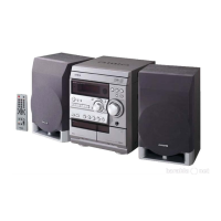
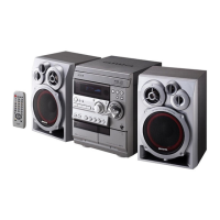
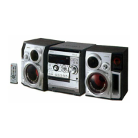
-43-
IC DESCRIPTION -1/1 (µPD780226GF-033-3BA) -1/2
Pin Name I/O
Description
Pin No.
1 O-MOTOR O DECK motor output.
2 O-SOL1 O DECK1 solenoid output.
3 O-SOL2 O DECK2 solenoid output.
4 O-STBY LED O Standby LED output. (Not used)
5 O-MUTE O System mute ON/OFF output.
6 O-KSCAN O Key scan timing output.
7 O-PLL_CE O PLL chip enable output for LC72131D-N.
8 I-TM_BASE I Time-base signal input.
9 O-TU-ON O Tuner ON/OFF output.
10 O-PB2 O DECK2 play back ON/OFF output.
11 O-VF ñ Not used.
12 I-AUTO1 I DECK1 detecting reel rotation switch input.
13 I-REA I DECK2 prevention for mistaken recording switch input.
14 I-CST1 I DECK1 cassette detect switch input.
15 I-CST2 I DECK2 cassette detect switch input.
16 I-AUTO2 I DECK2 detecting reel rotation switch input.
17 IC ñ GND.
18 VSS0 ñ GND.
19 VDD0 ñ Power supply input.
20 O-POWER O System power supply ON/OFF output.
21 I-JOG_A I JOG rotary encoder signal input (A/D).
22 I-JOG_B I JOG rotary encoder signal input (A/D).
23 I-VOL_A I VOL rotary encoder signal input (A/D).
24 I-VOL_B I VOL rotary encoder signal input (A/D).
25 I-SUBQ I CD SUBQ serial input.
26 I-WRQ I CD IC control input.
27 I-DRF I CD IC control input.
28 I-RDS_CLK I Tuner RDS clock output for BU1920FS.
29 I-RDS_DATA I Tuner RDS data output for BU1920FS.
30 RESET I Reset input.
31 O-DSC/O-DATA O Serial data latch output for BD3881FV / PLL data output for LC72131D-N.
32 O-CLK_SFT O MICON clock shift output.
33 I-IFC I Tune IF count serial data input.
34 I-RMC I System remote control signal input.
35 I-DISH I CD turntable photo sensor signal input.
36 I-STEREO I Tuner stereo detected input.
37 VDD1 ñ Power supply input.
38 X2 ñ 4.19MHz oscillator circuit.
39 X1 ñ 4.19MHz oscillator circuit.
40 VSS ñ GND.
41 AVDD ñ GND.
42 I-HOLD I Power failure detected input "L" to stop clock and hold memory.
43 I-CDSW I CD mechanical switch A/D converter input.
 Loading...