KUMO Quick Start Guide v4.2 2 www.aja.com
PS 1 & PS 2 Power Connectors
Power to the KUMO unit is supplied by an external power supply module that
accepts a 110-220VAC, 50/60Hz power input and supplies +12 VDC to KUMO via
connector PS1 or PS2. One power supply is provided, and it may be connected
to either of the two power connectors. An optional second power supply can
provide redundancy to help protect against outages.
IMPORTANT: The power connector has a latch, similar to an Ethernet connector. Depress
the latch (facing the outside edge of the KUMO device) before disconnecting the
power cable from the unit.
Power Loss Recovery
If KUMO experiences a loss of power, when power is restored the router returns
to the previous state of all source to destination crosspoints, and all configured
source and destination names are retained. If a KUMO control panel configured
with a KUMO router loses power, when power is restored the control panel’s
configuration is retained, and button tallies will return to their previous states.
RJ-45 Ethernet Connector
The RJ-45 Ethernet connector allows you to connect KUMO to an Ethernet
10/100/1000 Ethernet LAN using CAT5 cable and access KUMO’s built in web
server. Multiple configurations are possible, including standalone control, a
local LAN, or a WAN. This also allows control over the network using GVG Native
Protocol.
ID and Reset
The ID (Identification) LED lights when you use the web interface to identify the
KUMO unit you are controlling. The Reset button (pinhole) below the LED allows a
safeboot reset of the unit as explained in "Safeboot Reset" on page 28.
REF BNC Connector
The REF BNC connector is the looping input for synchronizing the crosspoint
switch timing of KUMO to your house video signals. Apply an analog NTSC, PAL,
or Tri-level sync signal to this input. Be sure to terminate the second BNC with a 75
Ohm terminator, or if you loop to other equipment terminate the last connected
device.
When reference is present, KUMO will switch at the SMPTE RP168 designated
switch point with respect to the reference input. If no reference is present, the
KUMO will switch at random times.
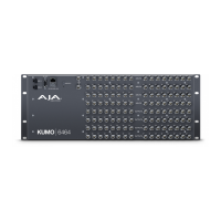
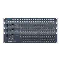
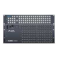
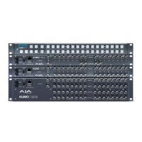
Video Inputs and Outputs
Depending on your KUMO model, up to 64 SDI video inputs and outputs can be
connected to the video input and output BNC connectors.
Normal Mode
In Normal mode, BNC inputs and outputs have a one-to-one relationship with the
SDI signals being routed.