IV.
ELECTRICAL ADJUSTMENT
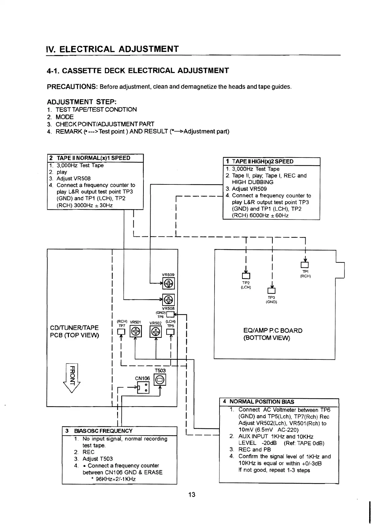
4-1. CASSETTE DECK ELECTRICAL ADJUSTMENT
PRECAUTIONS: Before adjustment, clean and demagnetize the heads and tape guides.
ADJUSTMENT STEP:
1.
TEST TAPEffEST CONDTION
2.
MODE
3.
CHECK POINT/ADJUSTMENT PART
4.
REMARK(•--->
Test
point)
AND RESULT (*-3>-Adjustment part)
2 TAPE
II
NORMAL(x)1
SPEED
1.
3,000Hz Test Tape
2. play
3.
Adjust VR508
4.
Connect a frequency counter to
play L&R output test point TP3
(GND) and TP1 (LCH),
TP2
(RCH) 3000Hz ± 30Hz
,----
1
I
I
1 TAPE
II
HIGH(x)2 SPEED
1.
3,000Hz Test Tape
2. Tape
II,
play; Tape
I,
REC
and
HIGH DUBBING
3. Adjust VR509
4.
Connect a frequency counter to
play L&R output test point TP3
(GND) and TP1 (LCH), TP2
(RCH) 6000Hz
± 60Hz
--L-------,--7---7
,---------.---1------1----
CDffUNER/TAPE
PCB
(TOPVIEW)
VR509
VR508
(GND)
TP6
(RCH)
VR501
9~
VR502 (LCH)
@9
I I
I I
L
____
_
CN106
r-0
I
3
BIAS
OSC
FREQUENCY
1.
No
input
signal, normal recording
test tape.
2. REC
3.
Adjust T503
4.
• Connect a frequency counter
between CN106 GND
& ERASE
* 96KHz+2/-1 KHz
-f
I
I
I
I
I
I
I
I
__
_
13
I
I
c3
6
I
I
TP1
(RCH)
TP2
[3
(LCH)
TP3
(GND)
EQ/AMP
P.C
BOARD
(BOTTOM VIEW)
4
NORMAL
POSITION BIAS
1.
Connect AC Voltmeter between TP6
(GNO) and TP5(Lch), TP7(Rch) Rec
Adjust
VR502(Lch), VR501(Rch) to
10mV
(6.5mV AC-220)
2.
AUX
INPUT 1 KHz and 1 0KHz
LEVEL
-20dB (Ref: TAPE 0dB)
3.
REC
and PB
4.
Confirm the signal level of 1KHz and
1 0KHz is equal or within +0/-3dB
If
not
good, repeat 1-3 steps
 Loading...