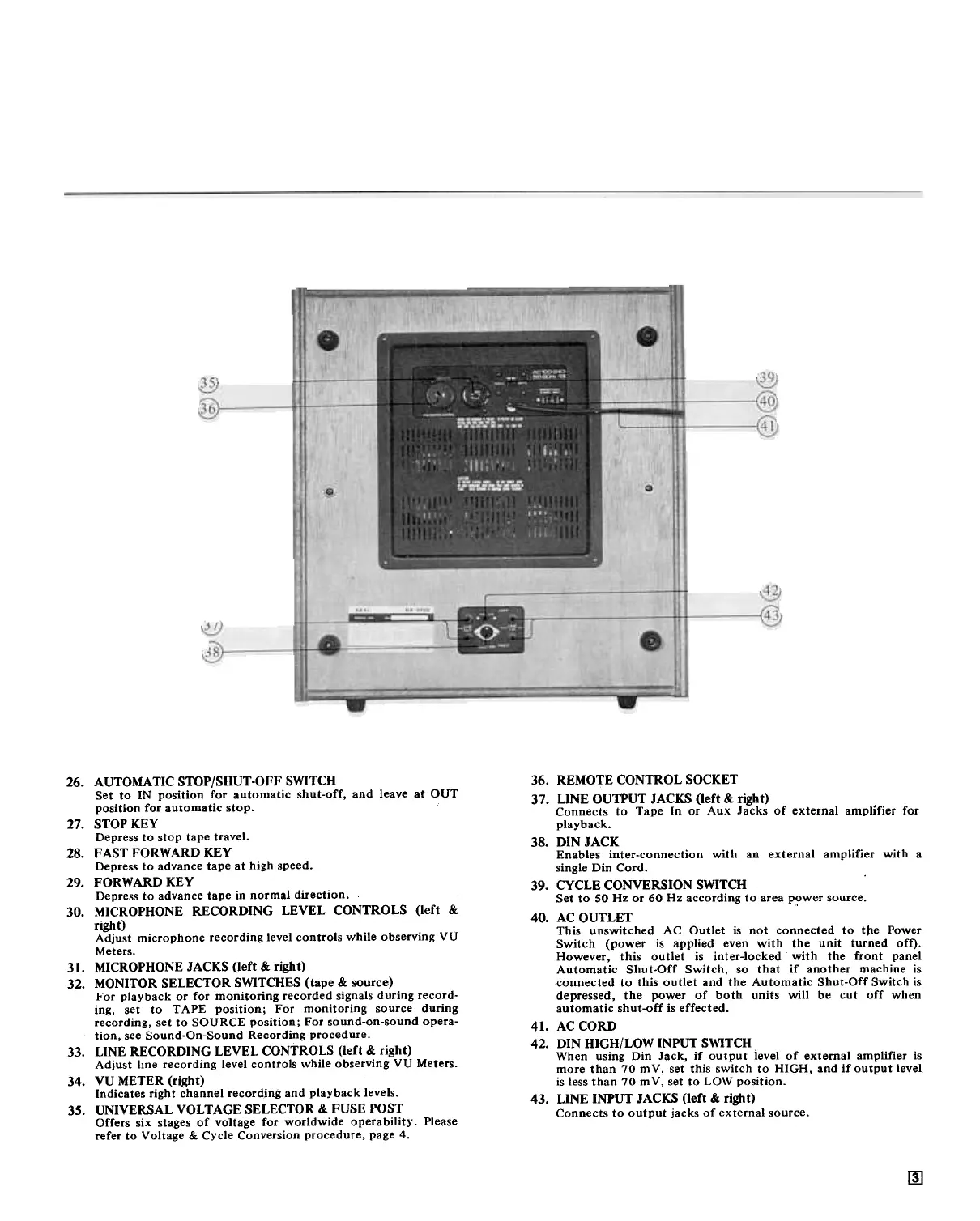
36. REMOTE CONTROL SOCKET
37. LINE OUTPUT JACKS (left & right)
Connects to Tape In or Aux Jacks of external amplifier for
playback.
38. DIN JACK
Enables inter-connection with an external amplifier with a
single Din Cord.
39. CYCLE CONVERSION SWITCH
Set to SO Hz or 60 Hz according to area P?wer source.
40. AC OUTLET
This unswitched AC Outlet is not connected to tpe Power
Switch (power is applied even with the unit turned off).
However, this outlet is inter-locked with the front panel
Automatic Shut-Off Switch, so that if another machine is
connected to this outlet and the Automatic Shut-Off Switch is
depressed, the power of both units will be cut off when
automatic shut-off is effected.
41. AC CORD
42. DIN HIGH/LOW INPUT SWITCH
When using Din Jack, if output ievel of external amplifier is
more than 70 mV, set this switch to HIGH, and if output level.
is less than 70 m V, set to LOW position.
43. LINE INPUT JACKS (left & right)
Connects to output jacks of external source.
26. AUTOMATIC STOP/SHUT-OFF SWITCH
Set to IN position for automatic shut-off, and leave at OUT
position for automatic stop.
27. STOP KEY
Depress to stop tape travel.
28. FAST FORWARD KEY
Depress to advance tape at high speed.
29. FORWARD KEY
Depress to advance tape in normal direction.
30. MICROPHONE RECORDING LEVEL CONTROLS (left &
right)
Adjust microphone recording level controls while observing vI)
Meters.
31. MICROPHONE JACKS (left & right)
32. MONITOR SELECTOR SWITCHES (tape & source)
For playback or for monitoring recorded signals during record-
ing, set to TAPE position; For monitoring source during
recording, set to SOURCE position; For sound-on-sound opera-
tion, see Sound-On-Sound Recording procedure.
33. LINE RECORDING LEVEL CONTROLS (left & right)
Adjust line recording level controls while observing VU Meters.
34. VU METER (right)
Indicates right channel record;ng and playback levels.
35. UNIVERSAL VOLTAGE SELECTOR & FUSE POST
Offers six stages of voltage for worldwide operability. Please
refer to Voltage & Cycle Conversion procedure, page 4.
~
 Loading...