EasyManua.ls Logo

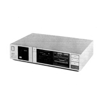
Akai GX-A5

Akai GX-A5
37 pages
To Next Page IconTo Next Page
To Previous Page IconTo Previous Page
Loading...
CAUTION:
Connect
a
resistor
(22
kohms)
between
LINE
OUT
and
GND,
while
PB
LEVEL,
PB
EQ,
REC
LEVEL
and
each
FREQUENCY
RESPONSE
adjustments.
Adjustment
Test
Tape
&
Adjustment
Ste
iy
Pi
|justmen
“P|
Item
Supply
Signal
|
Mode
Point
eis
Remaths
315Hz
—6.040.2dBm
1
|
PBLEVEL
or
PB
ae
or
333Hz
(ch)
|
_6.620.24Bm
VRI(Lch)
2
PBE
10kH:
PI
—21.0
+11
Q
Iz.
'B
VRIb(Reh)
21.0
+1.0dBm
Normal
Normal
3
Position
Blank
Tape
REC/PB
VR
6
(Lch)
1kHz,
10kHz
Frequency
1kHz,
10kHz
VR
6b
(Rch)
Flat
+0.3dBm
Response
—26.0dBm
CrO2 CrO2
Position
Blank
Tape
1kHz,
10kHz
$
Frequency
1kHz,
10kHz
REC/PB
ie
Flat
+1.0dBm
Response
—26.0dBm
Metal
Metal
Position
Blank
Tape
1kHz,
10kHz
5
|
Frequency
1kHz,
1okHz
|
RPC/PB
vee
Flat
#1,0dBm
Response
—26.0dBm
Normal
Blank
Tape
VR
3
(Leh)
6
REC
LEVEL
315Hz
REC/PB
VR
3b
(Rch)
—6.0+0.5dBm
—6.0dBm
Metal
REC
7
BIAS
Blank
Tape
or
FL
1
(ich)
Less
than
Filter
No
Signal
REC
FL
1b
(Rch)
—46dBm
Input
PAUSE
é
MPX
puaraiee
REC
FL2(Lch)
|
Less
than
Set
DOLBY
NR
SW
to
Filter
19kHz,
0dBm
PAUSE
FL
2b
(Rch)
~35dBm
DOLBY-B
or
DOLBY-C.
Meter
Waetas
REC
|
VR7(Lch)
ovu
Sensitivity
1kHz,
—6.0dBm
PAUSE
VR
7b
(Rch)
|
INDICATION
HX-A3X
ONLY.
Set
the
dbx
SW
to
dbx|
10
Gales
ad)
piesa
STOP
VR8
15mV+0.15mV
|
disc.
Connect
the
digital
ee
voltmeter
between
TP1
(and
TP2
(4).
NOTE:
1.
Above
adjustment
except
for
step
8
and
step
10,
adjustment
should
be
made
with
Dolby
NR
and
dbx
at
OFF
POSITION.
-2,
Use
the
following
cassette
measuring
tapes:
NORMAL
TAPE
:
Maxell
UDI
C-60
CrO2
METAL
TAPE
:
TAPE
:
TDK
SA
C60
TDK
MA
C-60
3.
Refer
to
Fig.
6-1,
for
above
adjustments.
SERVICE
MANUAL
GX-A5
[Xe
—————
rn
13

Related product manuals