EasyManua.ls Logo

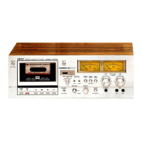
Akai GXC-750D

Akai GXC-750D
47 pages
To Next Page IconTo Next Page
To Previous Page IconTo Previous Page
Loading...
y
ADJUSTMENT
SCREWS
PINCH
ROLLER
Fig.
6
СИНО
CASSETTE
ТАРЕ
PLAY
POSITION
HEAD
BASE
PAUSE
POSITION
.PLAY
PLUNGER
INSTALLATION
POSITION
ADJUSTMENT
(Refer
to
Fig.
6)
The
clearance
between
the
head
base
and
head
clutch
plate
when
the
plunger
is
moved
as
indicated
in
Fig.
6
at
stop
mode
should
be
approximately
1.0
mm.
If
not,
adjust
play
plunger
position
with
the
adjustment
screws
in
the
direction
as
indicated
by
the
arrow
mark.
ADJUSTMENT
SCREW
Fig.
7
.
PAUSE
PLUNGER
INSTALLATION
POSITION
ADJUSTMENT
(Refer
to
Fig.
7)
With
the
tape
loaded,
the
Pause
Plunger
Solenoid
is
not
completely
pulled
if
the
head
base
does
not
lower
at
all
when
the
mode
is
changed
from
PLAY
to
PAUSE.
In
order
to
allow
Pause
Plunger
to
function
completely
and
still
have
the
head
not
lowered
too
much,
the
head
base
should
lower
only
0.1
mm
(lower
only
slightly)
when
the
mode
is
changed
from
PLAY
to
PAUSE
as
shown
in
Fig.
7.
If
you
find
that
the
plunger
function
is
not
complete,
adjust
by
lowering
the
Pause
Plunger
Installation
Position
approximately
0.1
mm
using
the
adjustment
Screw.
EE
дд
15

Other manuals for Akai GXC-750D

Related product manuals