OPERATING MANUAL 8 (112)
Document-ID: 947422-000 Multi Version: C0
EN
7.1 Indications on the Receiver
The Sesam 800 RXM model has LED indicators that indicate dierent parameters (see g. 1 for
positions of the LEDs).
The indications on the LEDs are as follows:
Power LED (see
1
in g. 1)
Indicates whether the receiver is powered on or not.
LED 5 Squelch (see
5
in g. 1)
Indicates a detected signal on the operating frequency band.
LED 6 Status (see
6
in g. 1)
Indicates that information from a transmitter paired with the receiver has been received.
LED 7 Learn (see
7
in g. 1)
Indicates if the transmitter is in Learn Mode. In Learn Mode LED 7 is lit. In Conguration
Mode LED 7 is slowly blinking.
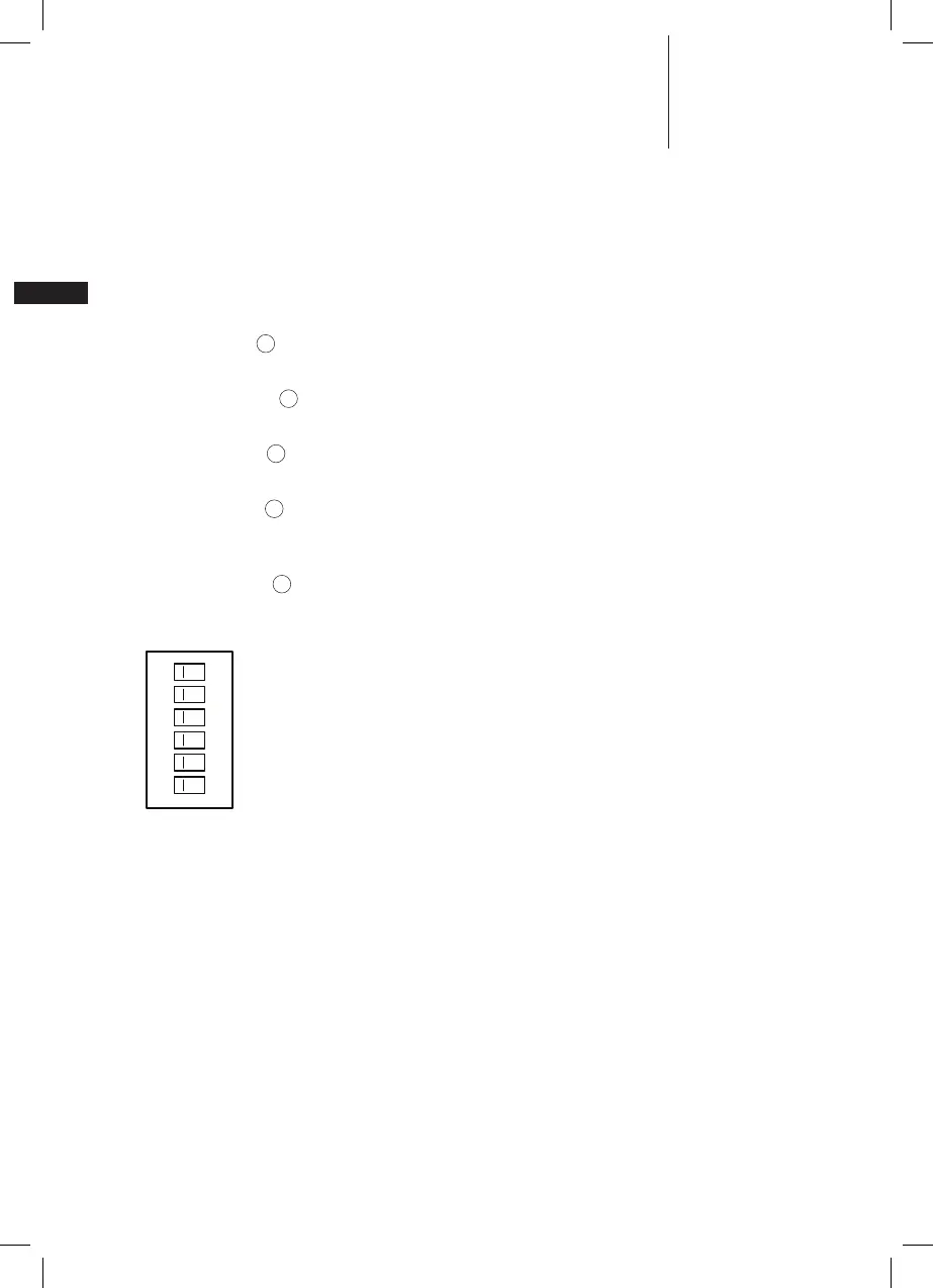
Outputs LEDs (see
10
in g. 1)
Indicates the state of outputs 1...6. Output LED 1 is the bottom one, output LED 6 is the top
one. An activated output is indicated by a LED in ON state.
6
5
4
3
2
1
Output 6
Output 5
Output 4
Output 3
Output 2
Output 1
Figure 2. Output LED numbering and relationship with output terminals
8 INSTALLATION OF THE RECEIVER
The permanent installation of the receiver must include fuses that protect the equipment and
wiring from over current and short-circuit. The power supply to the receiver must be fused with
3A as close to the battery as possible. The cable must be of outer diameter 6-12 mm and each
the power conductor at least 0.75mm
2
. Max cable length 5 meters.
 Loading...