OPERATING MANUAL 9 (112)
Document-ID: 947422-000 Multi Version: C0
EN
8.1 Mounting Steps
Step 1
Select a location that is within the environmental limitations of the receiver and where it is
dicult for unauthorized persons to obtain access to the receiver. Mount the receiver with the
cable glands facing downwards.
If possible mount the receiver inside a control cabinet. Note that this is only possible if the cabi-
net is made out of plastic or materials that not have a negative eect on radio emissions.
Step 2
Drill 4 holes (for measures see g. 11). Mount the receiver.
Step 3
Connect wiring for output signals and power supply. Use cable ties to secure the wires and
ensure that the wiring will not be aected by abrasion, heat and/or exhausts.
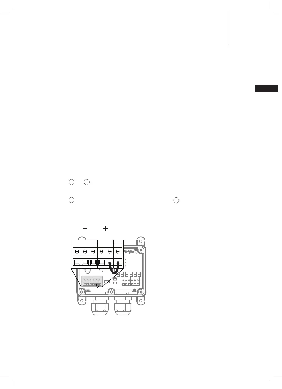
Connect 12-24 V DC (+) to position 3 and ground (-) to position 2
(see
3
and
2
in g 1).
Connect the equipment to be controlled to output terminals 1...6
(see
11
in g. 1) and equipment ground to position 2 (see
2
in g. 1). If the outputs are to be
pow ered by the same 12-24 V DC supply as the receiver place a jumper between the Output
Power Input (SW) and Positive (+) 12-24 V DC using a 0,75 mm
2
cable (see g. 3).
PB-Free
PB-Free
P0
YWW
941551
}
}
Figure 3. Conguring internal supply of output power
 Loading...