AKO-D14601:
120 V~ +8% -12%
50 / 60 Hz
AKO-D14602:
230 V~ ±10%
50 / 60 Hz
S1
21
3
4
5
6
AKO-D1460x
Alarm delay
These delays prevent the display of specific alarms while allowing the unit to recover normal operation after certain
events.
-Start-up delays (A3): Delays activation of temperature alarms on power-up (start-up or after a power failure). This
allows avoiding continuous alarms upon start-up
-Delay after defrost (A4): Delays activation of temperature alarms post-defrost.
-Delay of max/min temperature alarm (A5): Delays activation of maximum (A1) and minimum (A2) temperature
alarms from the moment temperature probe 1 reaches the set value.
-Delay of external alarm / activation (A6): Delays the activation of the external alarm from
the moment the digital input becomes active.
-Delay of external alarm / deactivation (A7): Delays the deactivation of the external alarm
from the moment the digital input becomes inactive.
-Door opening alarm rela
5.1.- Thermometers
severe external alarm
severe external alarm
y (A12): Delays activation of the open door opening detection alarm.
Alarm relay configuration (Depending on model)
If your equipment has an alarm relay (see page 6) or auxiliary relay configured as an alarm (P6=2), the parameter A9
allows specifying the relay status when an alarm is triggered:
A9=0 relay active (ON) in case of alarm (no alarm OFF); A9=1 Inactive relay (OFF) in case of alarm (no alarm ON)
5.- Wiring
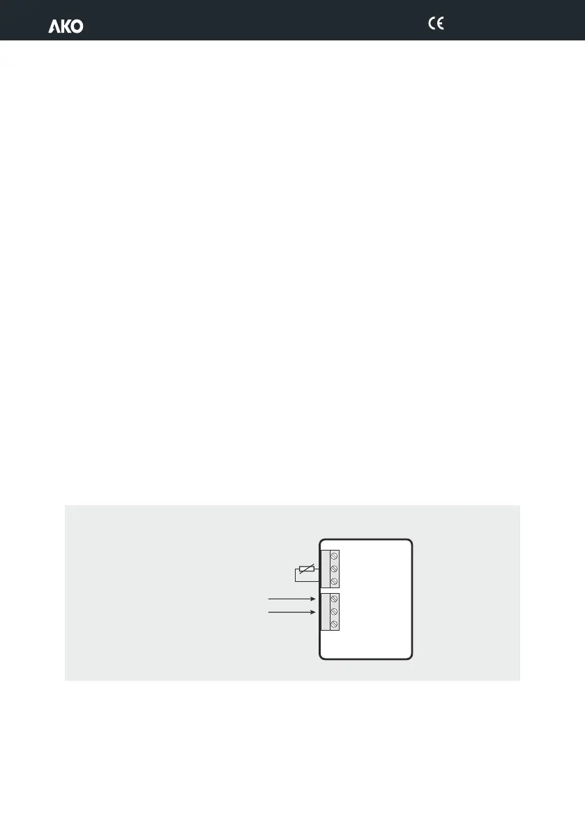
The probe and its cable should NEVER be installed in the same conduit as power, control or supply cables.
Legend:
ŸS1: Probe 1, temperature in the chamber or cabinet
ŸS2: Probe 2, defrost.
ŸS3: Probe 3, temperature of product / 2nd defrost.
ŸDI1/DI2: Digital Input 1 / Digital Input 2.
18
D146H002 Ed.02


 To Next Page