2.4 CABLE(S) INSTALLATION (J2 Connector)
2.4.1 Monitor/Turret Cable
Monitors and Turrets designed for use with the Universal II come fitted with a harness and connector ready for direct plug-in to the
Universal II. While these are configured for “plug and play” installation, removal of the connector to run through a bulkhead may be
necessary from time to time. In that event, or in the event of troubleshooting, Table 2-2 is provided for reference.
2.4.2 General Monitor/Turret Connector Pin-out
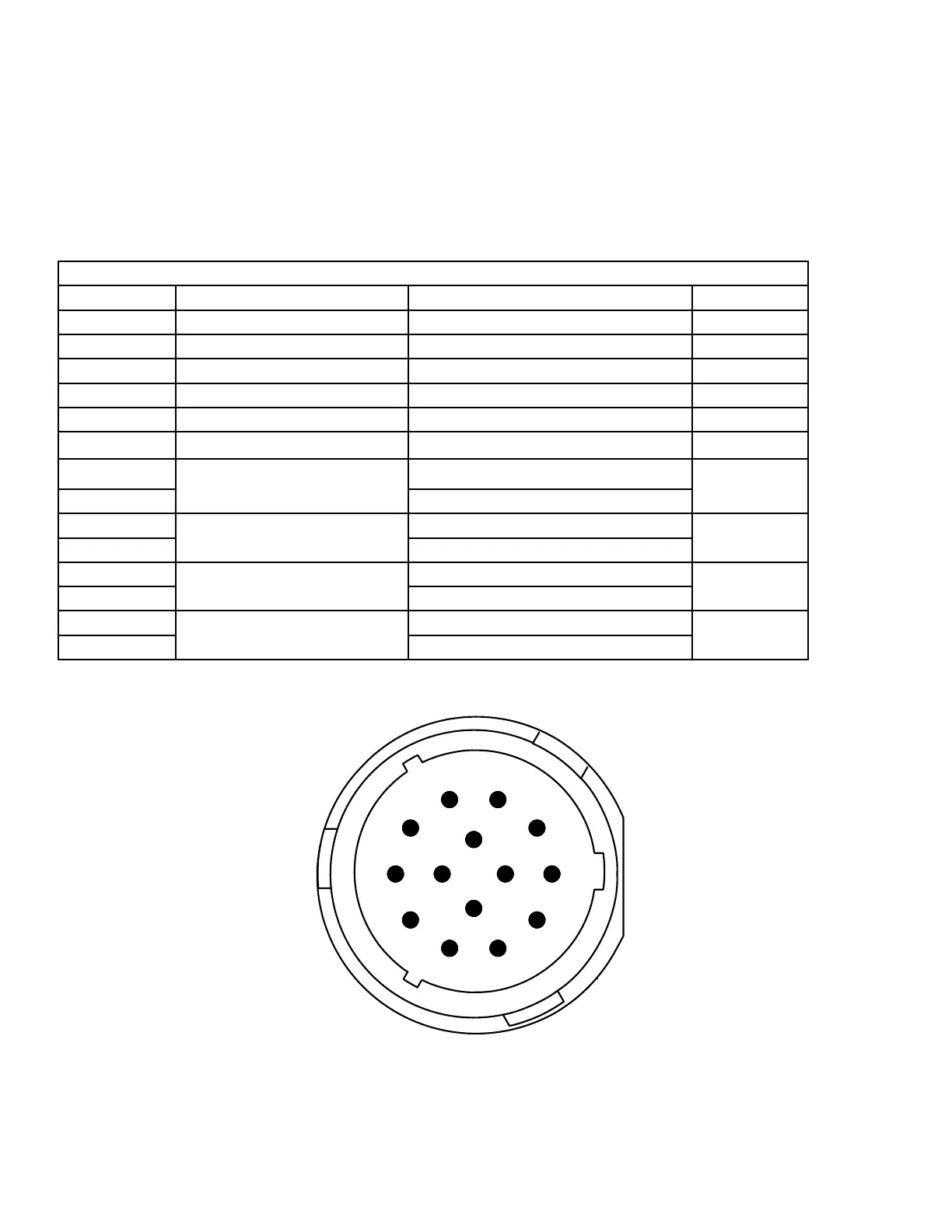
14 Pin Male 16 AWG Connector – HDP26-18-14SE-L017
Pin Number Type Potential Function Comments
A Analog Common (Ground)
B Analog, Switch, PWM In #1 Rotation Position
C Analog, Switch, PWM In #2 Elevation Position
D Analog, Switch, PWM In #3 Inclination Sensor (Auto-Level)
E Analog Exc. (+5 volts)
F Appliance Loop (Tied to Gnd if non “Smart Harness”) (LIN Bus)
G
H-Bridge
Axis #1
+ (Up)
Elevation
H - (Close)
J
H-Bridge
Axis #2
+ (Left)
Rotation
K - (Right)
L
H-Bridge
Axis #3
+ (Fog)
Pattern
M - (Stream)
N
H-Bridge
Axis #4
+ (Low)
Gallonage
P - (High)
Table 2-2 Monitor/Turret Connector Pin-out
Figure 2-2 Monitor Connector (Looking into Universal II)
7.50"
4.0"
UNIVERSAL CONTROL II
STYLE 6032
12/24 VOLTS DC
AKRON BRASS COMPANY
WOOSTER, OHIO
www.akronbrass.com
A
B
C
D
E
F
G
H
J
K
L
M
N
P
1
2
3
4
5
6
7
8
9
10
11
12
13
14
15
16
17
18
19
20
21
22
23
24
25
26
27
28
29
Pin 1 - Vehicle Battery +
Pin 2 - Vehicle Battery -
Pin 3 - Aux. Battery +
Pin 4 - Aux. Battery -
Pin 5 - H-Bridge
Pin 6 - Axis #5
Pin 7 - Output #1
Pin 8 - Output #2
Pin 9 - Output #3
Pin 10 - Bi-stable Relay - COM
Pin 11 - Contact Output - N.O.
Pin 12 - (Form C) - N.C.
Pin 13 - Switch Input #1
Pin 14 - Switch Input #2
Pin 15 - Switch Input #3
Pin 16 - Switch Input #4
Pin 17 - Switch Input #5
Pin 18 - Switch Input #6
Pin 19 - Switch Input #7
Pin 20 - Switch Input #8
Pin 21 - Switch Input #9
Pin 22 - Aux. Power (1 Amp)
Pin 23 - Data + Vehicle
Pin 24 - Data - Can
Pin 25 - Common (Ground)
Pin 26 - Data + Proprietary
Pin 27 - Data - Can
Pin 28 - Data + VMUX-COM A
Pin 29 - Data - Network-COM B
Pin A - Analog Common
Pin B - Analog, Switch, PWM In #1
Pin C - Analog, Switch, PWM In #2
Pin D - Analog, Switch, PWM In #3
Pin E - Analog Exc.
Pin F - Appliance Loop - LIN
Pin G - H-Bridge
Pin H - Axis #1
Pin J - H-Bridge
Pin K - Axis #2
Pin L - H-Bridge
Pin M - Axis #3
Pin N - H-Bridge
Pin P - Axis #4
READ OPERATING INSTRUCTIONS BEFORE USE
NOTE:
THIS DETAIL IS FOR REFERENCE ONLY AND SHOULD NOT
BE USED TO CREATE THE GRAPHICS.
USE THE ADOBE ILLUSTRATOR FILE TO PRODUCE
THE ACTUAL SILKSCREEN GRAPHICS.
MATERIAL:
0.010 POLYCARBONATE WITH
3M 9471 PRESSURE SENSITIVE ADHESIVE.
10