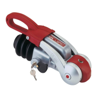
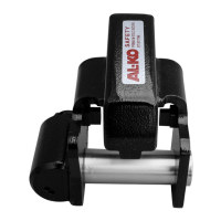
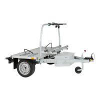
KIT CONTENTS (Fig. 1):
1) Replacement handle
2) Torx spanner
3) Fixing Screw
ASSEMBLY:
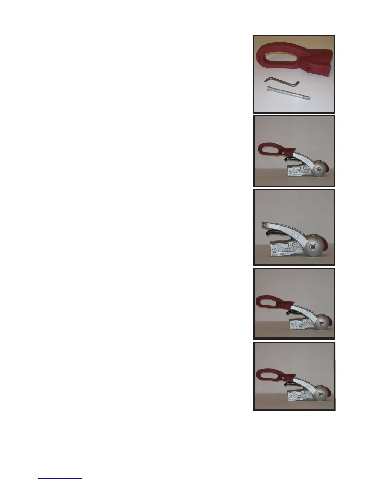
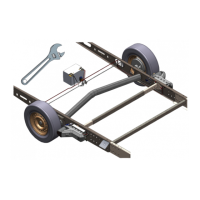
1) Removal of existing red handle from the stabiliser
lever arms:
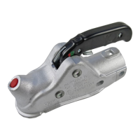
a) using the torx spanner provided, undo and remove the
xing screw located on the side of the red handle (Fig.
2).
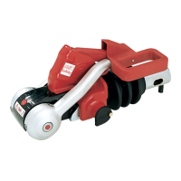
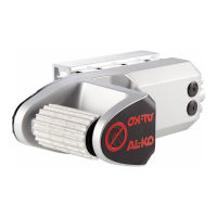
b) the red handle should now pull off the stabiliser lever
arms (Fig. 3).
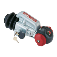
2) Fitment of new handle
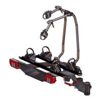
a) ensure both stabiliser lever arms are level
b) Push the new handle on to the lever arms (Fig. 4).
c) Insert xing screw and tighten using the torx spanner
(Fig. 5).
The handle is now ready for use.
Part No: 1552888 Rev 07/09
1)
3)
Fig. 3
AL-KO Kober Ltd
South Warwickshire Business Park, Kineton Road, Southam, Warwickshire, CV47 0AL
Phone: 01926 818500 Fax: 01926 818562 www.al-ko.co.uk
Fig. 1
2)
Fig. 2
Fig. 4
Fig. 4
Fig. 5
KIT CONTENTS (Fig. 1):
1) Replacement handle
2) Torx spanner
3) Fixing Screw
ASSEMBLY:
1) Removal of existing red handle from the stabiliser
lever arms:
a) using the torx spanner provided, undo and remove the
xing screw located on the side of the red handle (Fig.
2).
b) the red handle should now pull off the stabiliser lever
arms (Fig. 3).
2) Fitment of new handle
a) ensure both stabiliser lever arms are level
b) Push the new handle on to the lever arms (Fig. 4).
c) Insert xing screw and tighten using the torx spanner
(Fig. 5).
The handle is now ready for use.
Part No: 1552888 Rev 07/09
1)
3)
Fig. 3
AL-KO Kober Ltd
South Warwickshire Business Park, Kineton Road, Southam, Warwickshire, CV47 0AL
Phone: 01926 818500 Fax: 01926 818562 www.al-ko.co.uk
Fig. 1
2)
Fig. 2
Fig. 4
Fig. 4
Fig. 5