Do you have a question about the AL-KO AKS 2004 and is the answer not in the manual?
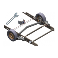
Undo fixing screw using the torx spanner and remove the red handle from the stabiliser lever arms.
Ensure lever arms are level, push new handle on, and tighten fixing screw with the torx spanner.
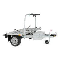
This document provides assembly instructions for the AL-KO replacement AKS 2004/3004 stabiliser handle. It outlines the general guidelines, kit contents, and step-by-step assembly process for replacing the handle on AL-KO AKS 2004 and AKS 3004 stabilisers.
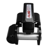
The AL-KO replacement AKS 2004/3004 stabiliser handle is designed to replace an existing handle on AL-KO AKS 2004 and AKS 3004 stabilisers. The handle is a crucial component for operating the stabiliser, which is used to enhance the stability of a caravan or trailer when coupled to a towing vehicle. The stabiliser works by applying friction to the tow ball, thereby reducing snaking and pitching movements during travel. The handle facilitates the engagement and disengagement of the stabiliser's friction pads onto the tow ball.
The replacement handle ensures the continued proper operation of the stabiliser, allowing users to maintain the safety and stability benefits provided by the AKS 2004/3004 system. Its primary function is to provide a secure and ergonomic grip for the user to manipulate the stabiliser's lever arms, which in turn control the friction pads.
| Brand | AL-KO |
|---|---|
| Model | AKS 2004 |
| Category | Automobile Accessories |
| Language | English |