Chapter 3 Components and Power Supply
The following chapter provides detailed information on the chassis of the OA5710V router and its components. This
information includes:
• Components.
• Information on assembly.
• Installation and removal of modules.
• Power supply.
• RST button.
• Data connection.
• SIM card installation.
3.1 Components
3.1.1 Front Panel
The following figure shows the front panel. The only thing to be found here are the 3G antenna connectors.
Fig. 1: Front Panel
The front panel elements are as follows:
Front Panel Elements
Item Description
A Main antenna for the OA5710V cellular module.
B Auxiliary antenna 2 for the OA5710V cellular module.
C Auxiliary antenna 1 for the OA5710V cellular module.
D RJ-45 connector, which provides access to the OA5710V local console for config-
uring and monitoring purposes.
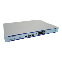
3.1.2 Rear Panel
The following figure shows the rear panel. Here you can see the rest of connectors for the OA5710V router.
Fig. 2: Rear Panel
3 Components and Power Supply Alcatel-Lucent Enterprise
4 OA5710V Router