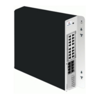
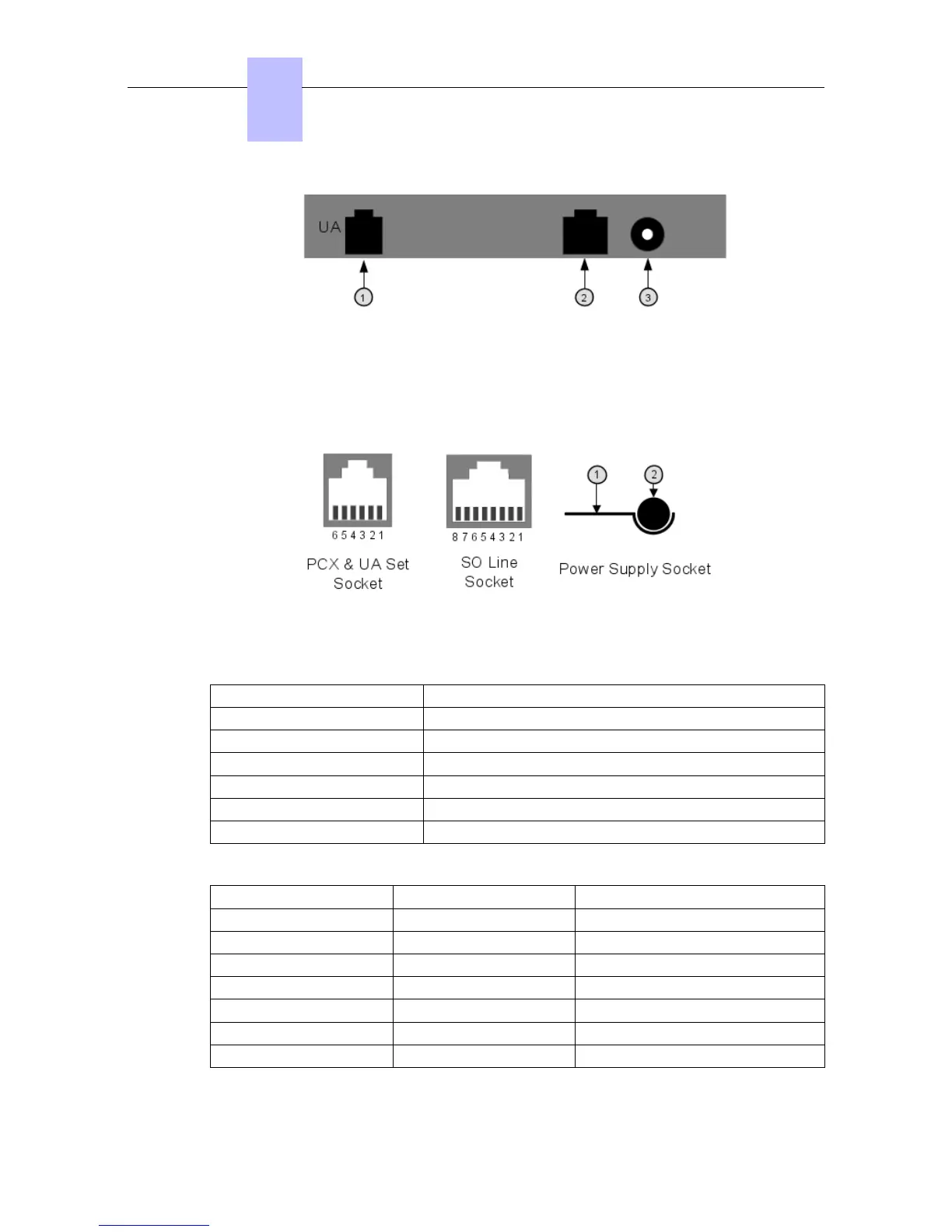
Figure 4.64: Rear Panel Details
1. RJ11 socket for UA line
2. RJ45 socket for S0 bus
3. Power supply socket
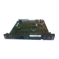
Figure 4.65: Socket Details
PCX and digital set socket:
Pin Description
1 Not used
2 External Ringing 1
3 UA line 1
4 UA line 2
5 External Ringing 2
6 Not used
S0 bus RJ45 socket:
Pin Description Polarity
1 Not used
2 Not used
3 Transmission +
4 Reception +
5 Reception —
6 Transmission —
7 Not used
Chapter
4
&'(
4-90
 Loading...