Do you have a question about the Alfa Laval FrontLine WideGap 100 and is the answer not in the manual?
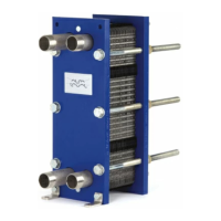
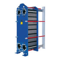
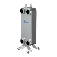
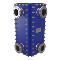
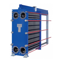
The device is a gasketed plate-and-frame heat exchanger, designed for efficient heat transfer between two separate fluids. It consists of a pack of corrugated metal plates with portholes for the input and output of these fluids. Heat transfer occurs through the plates, which are assembled between a frame plate and a pressure plate and compressed by tightening bolts. Each plate is fitted with a gasket that seals the channel and directs the fluids into alternate channels. The corrugation of the plates promotes fluid turbulence, enhancing heat transfer, and supports the plates against differential pressure.
The heat exchanger facilitates the transfer of thermal energy from one medium to another without direct contact between the fluids. This is achieved by the design of the plate pack, where the corrugated plates create a series of parallel flow channels. The fluids flow in alternate channels, allowing heat to be exchanged across the thin metal plates. The multi-pass configuration, achieved by using turning plates with unholed ports, allows for changes in the flow direction of one or both fluids, which can be beneficial for processes requiring longer heating periods or specific flow patterns. Partition plates may be used in some multi-pass units to support unholed ports in turning plates, and transition plates prevent media from contacting the partition or pressure plates.
The heat exchanger is designed for installation on a flat foundation that provides adequate support to the frame. It requires sufficient free space around it for maintenance activities, such as lifting plates in and out, and for accessing the lower tightening/locking bolts. For ease of disconnection, an elbow should be fitted to the connection in the pressure plate, directed upwards or sideways, with another flange located just outside the heat exchanger's contour. Shut-off valves are recommended in all connections to allow the heat exchanger to be isolated for opening and maintenance. Various types of connections can be used for the piping system, with flanged connections typically attached with pin bolts. It is crucial to avoid excessive loads from the piping system on the heat exchanger.
During installation, it's important to ensure that all foreign objects are flushed out of the piping system before connection. The tightening bolts must be firmly secured, and the plate pack must have the correct dimensions as specified in the PHE drawing. To prevent water hammer, fast-closing valves should not be used, and care must be taken to ensure no air remains inside the heat exchanger. Safety valves should be installed according to relevant pressure vessel regulations. Protection sheets are recommended to cover the plate pack and guard against leakage of hot or aggressive fluids. If the surface temperature is expected to be hot or cold, insulation should be applied to prevent personnel injuries.
Start-up procedures involve checking for visible leakages, ensuring the heat exchanger's temperature is within the specified range for the gaskets, and slowly increasing flow rates to avoid pressure surges. Centrifugal pumps should be started with valves closed and operated smoothly. Vent valves should be opened during start-up to expel air and closed once all air is out. Temperature changes, especially with media over 100°C, should be gradual to prevent stress on the heat exchanger. During operation, flow rates should be adjusted slowly, and media temperatures and pressures must remain within the limits stated on the name plate and PHE drawing. In case of safety-endangering failures, flow to the heat exchanger should be turned off to decrease pressure and stop heat transfer. Shut-down involves slowly closing valves and stopping pumps, draining the unit if it will be out of service for an extended period, and rinsing and drying plates and connections as needed. Vacuum in the heat exchanger should be avoided by opening vent valves during shut-down.
Regular maintenance is crucial for the heat exchanger's longevity and optimal performance. This includes keeping the carrying and guiding bars clean and greased, ensuring tightening bolts are clean, greased, and firmly tightened, and verifying the correct plate pack dimensions. The plates require regular cleaning, with frequency depending on media type and temperature. Cleaning-in-place (CIP) equipment allows for cleaning without opening the unit, aiming to remove fouling, descale lime deposits, passivate cleaned surfaces, and neutralize cleaning liquids. Proper protective equipment, such as safety boots, gloves, and eye protection, must be used when handling cleaning agents, which can be corrosive.
For manual cleaning, the heat exchanger must be opened. Before opening, the warranty conditions should be checked, and the unit must be cooled down to approximately 40°C (104°F) if hot. Protective equipment is necessary during manual cleaning. The bolt configuration, with tightening bolts (TB) and locking bolts (LB), is important for opening and closing. Locking bolts are removed first, followed by loosening tightening bolts diagonally to keep the frame and pressure plates parallel. The plate pack can then be opened by sliding the pressure plate along the carrying bar. Plates can be cleaned manually with a soft brush and running water, or with cleaning agents for stubborn deposits. If cleaning agents are used, plates must be removed from the heat exchanger, and care must be taken to avoid damaging gaskets or gasket glue.
After cleaning, the heat exchanger is reassembled by ensuring all sealing surfaces are clean, bolts are lubricated, and gaskets are correctly attached and positioned. If plates were removed, they must be reinserted in alternate directions, with gaskets facing the frame or pressure plate as specified on the plate hanging list, following any diagonal markings made during disassembly. The plate pack is then compressed by tightening the bolts evenly and diagonally until the correct dimension A is reached. A hydraulic pressure test is recommended after any maintenance involving plate or gasket removal or exchange to confirm internal and external sealing. This test should be performed at the operating pressure but not exceeding the design pressure.
Regasketing procedures involve opening the heat exchanger, removing old gaskets, cleaning sealing surfaces, and attaching new gaskets. For Clip-on/ClipGrip gaskets, tabs are slipped under the plate edge. For Clip-ad gaskets, adhesive tape is applied along the sides of the plates using a tape gun, and then the gasket prongs are slipped under the plate edge. Glued gaskets require specific glue recommended by Alfa Laval, with separate instructions provided. Sharp tools should not be used when removing glued gaskets to prevent plate damage. After regasketing, the heat exchanger is closed following the standard closing procedure.
| Model | FrontLine WideGap 100 |
|---|---|
| Category | Industrial Equipment |
| Type | Plate Heat Exchanger |
| Material | Stainless Steel |
| Maximum Operating Temperature | 150°C |
| Maximum Operating Pressure | 10 bar |
| Connection Size | DN100 |
| Weight | Varies based on configuration |