3 Installation
The valve sizes DN125-150 are very heavy.
Therefore Alfa Laval recommends manufacturing and usage of auxiliary equipment. A proposal is given below.
Please note that the auxiliary equipment cannot be supplied by Alfa Laval.
The items refer to the parts list and service kits section.
3.2 Recommended auxiliary equipment
Step 1
For lifting the valve
Screw an eye bolt (6 mm) (1/4”) into top pin (23). Using a small
hook crane or similar, lift the valve by the eye bolt.
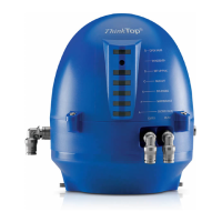
Trestle:
- The purpose of the trestle is to support the valve during dismantling and reassembly.
- The trestle is made of a base plate, two support plates, two rubber linings and four bolts.
- The rubber linings are attached to the support plates so that the valve/actuator will rest on these.
- To prevent the valve from turning during dismantling and assembly the trestle must be made with the correct measurements
(see below). All measurements are in mm.
TD425-159_1
10mm(0.4”)
50mm(2”)
50mm(2”)
TD425-160_1
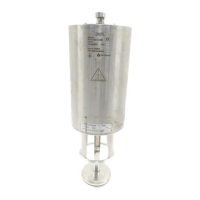
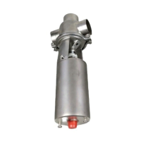
Trestle
Side view
TD425-161_1
250mm(9.8”)
250mm(9.8”)
101.5mm(4”)
R99.5mm(3.9”)
TD425-162_1
Top view End view
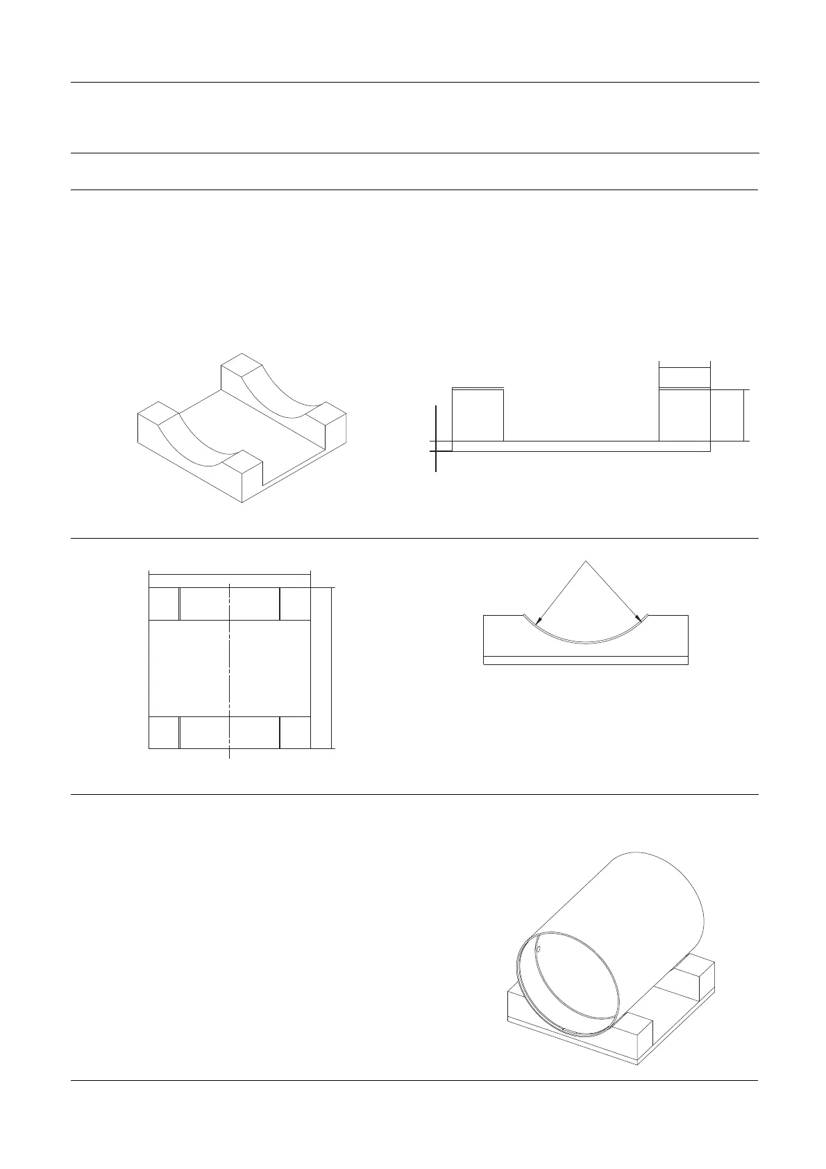
Step 2
1. Place the valve in the trestle.
2. Make sure that the actuator rests on the rubber linings on the
trestle support plates.
3. Dismantle/assemble the valve.
TD425-163_1
8