5 Maintenance
This page is not applicable for ATEX applications.
For ATEX application see ATEX addendum
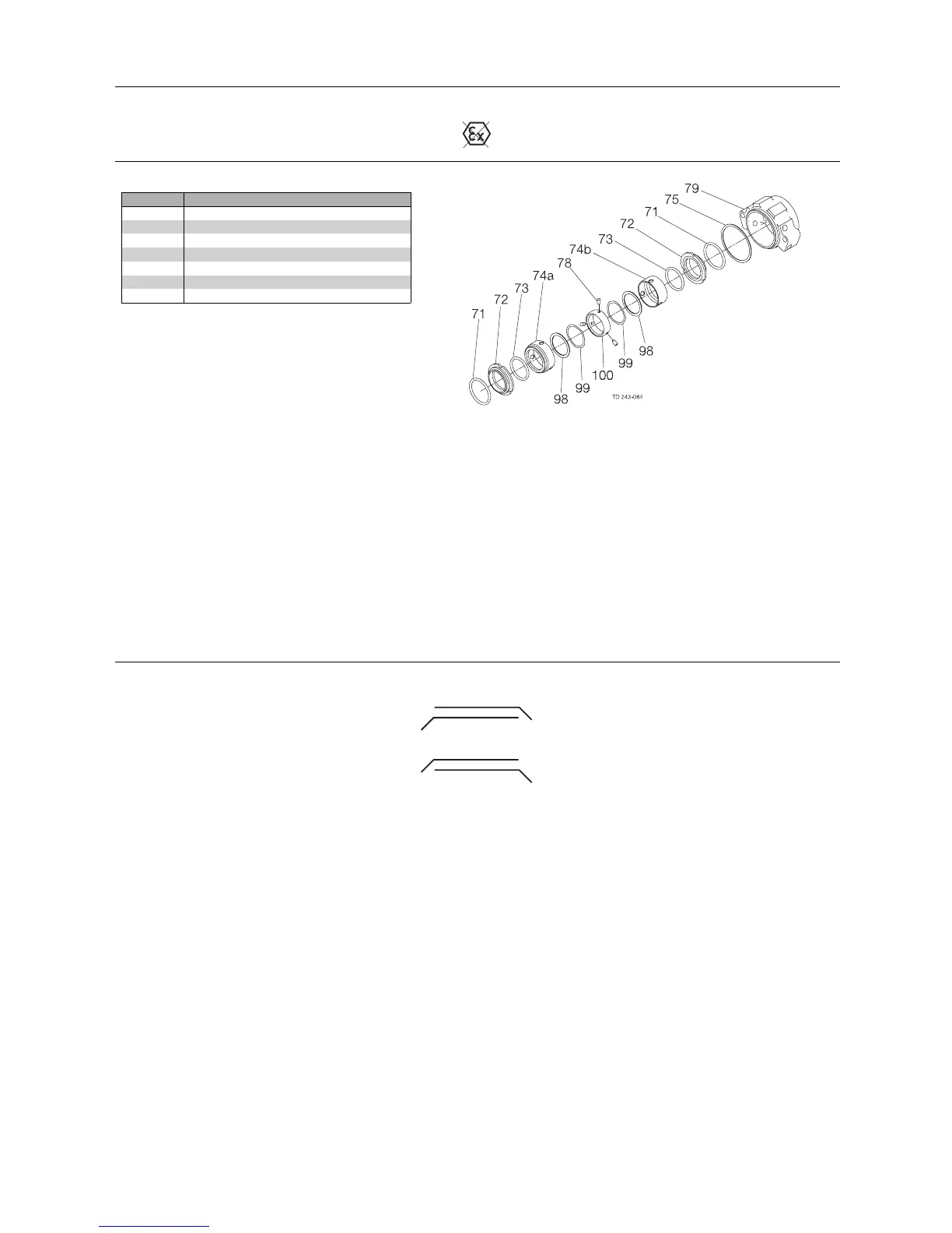
5.5.3 R90 Double flushed mechanical seal
Item
Description
71
Stationary seal ring O-ring
72
Stationary seal ring
73
Rotary seal ring O-ring
74a
Rotary seal ring assembly - inboard
74b
Rotary seal ring assembly - outboard
75
Seal housing O-ring
79
Seal housing
The Rotary Seal Assembly Inboard (74A) comprises of rotary seal ring,
washer (98), wave spring (99) and drive ring (100). The Rotary Seal
Assembly Outboard (74B) comprises of rotary seal ring, grub screw
(78), washer (98) and wave spring (99).
Seal removal:
1. Ensure the flush media is turned off and disconnect the flushing pipework.
2. Remove rotorcase cover and rotors.
3. Turn the drive shaft until the drive ring grub screws (78) are visible through the flushing connections.
4. Loosen the grub screws.
5. Remove the rotorcase.
6. Remove seal housings (79) complete with rotary seal assemblies (74A and 74B) and outboard stationary seals.
7. Extract the seal housing O-ring (75), stationary seal ring (72) and ‘o’ ring (71) from the rotorcase.
Seal fitting:
Ensure seal orientation is correct.
Outboard
Inboard
Series 1, the outboard seal fits over the
inboard seal.
Inboard
Outboard
Series 2-6, the inboard seal fits over the
outboard seal.
1. Lightly lubricate O-rings (71 and 73) with ap
propriate grease and fit to rotary seal assemblies and stationary seal rings
(74A, 74B and 72).
2. Fit stationary seals into the rotorca
se bores and seal housings (79).
3. Fit O-ring (75) into the
rotorcase bores.
4. Wipe clean the sealin
g faces with solvent.
5. Locate rotary seal
assemblies and fit the seal housings to the rotorcase ensuring that the grub screws (78) are accessible
so they can be tig
htened.
6. Refit the roto
rcase.
7. Turn the dri
ve shaft until the grub screws are visible through the flushing connections.
8. Tighten t
hegrubscrewstotherecommendedtorquefigurein.
9. Refit t
he rotors and rotorcase cover.
29
 Loading...