5 Ins tallation
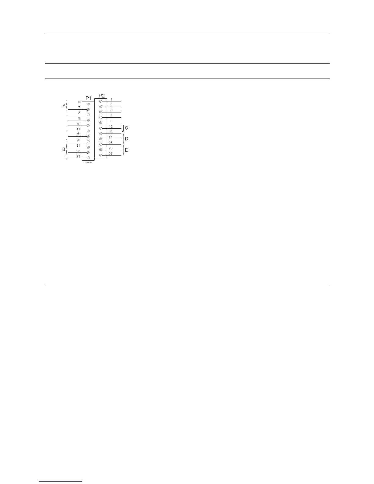
5.4 Electrical connection, internal
A
Bus Connection C PWM Jumper*
*)
Terminals 24, 25, 26 and 27 can be used for external seat lift sensors as well as for any digital input. Always use an external
PNP sensor. Two external signals can be connected, they are associated with feedback signal 3 (seat lift 1) and 4 (seat lift
2). External sensor must always be a 8-30 VDC PNP 3 wire sensor. Connect (-) common on terminal 27, and (+) common
on terminal 26. The signals from the external sensors are associated as follows: sensor signal on terminal 24 (seat lift 1)
associated with feedback 3 (seat lift 1), and sensor signal on terminal 25 (seat lift 2) associated with feedback 4 (seat lift 2).
**) Jumper present = PWM. See section 3.1.3 “Technical specifications solenoid valves”.
***)
Internal connections: Terminals for connection for the solenoids mounted internally in the control head. The number of
solenoids actually mounted in the control head could be 0 - 3. The signals are taken directly from the terminal row.
****) If using extern
al sensor, the sensor must be active/activated when performing a set-up routine of the control head.
19
 Loading...