4.2 Electrical installation
1
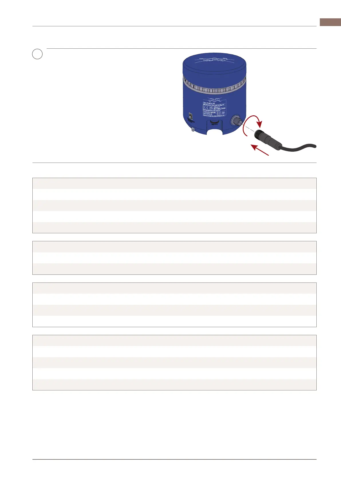
Fit the cable to the M12 connector and
tighten it using a 14 mm wrench (0.6...1.5
Nm).
Wiring diagrams
Terminals V20 Digital-IO 24V
(M12, pin 1) 24V
(M12, pin 2) Valve de-energised (DE-EN)
(M12, pin 3) GND
(M12, pin 4) Main valve energised (EN)
Terminals V20 AS-interface
(M12, pin 1) AS-i +
(M12, pin 3) AS-i –
Terminals V20 IO-Link
(M12, pin 1) L + 24V
(M12, pin 3) L-GND
(M12, pin 4) IO-Link
Terminals V20 Digital-IO 24V Retrofit
(M12, pin 1) GND
(M12, pin 2) Main valve energised (EN)
(M12, pin 3) Valve de-energised
(M12, pin 4) 24V
200008387-1-EN-GB 13
Installation 4 EN

 Loading...