18
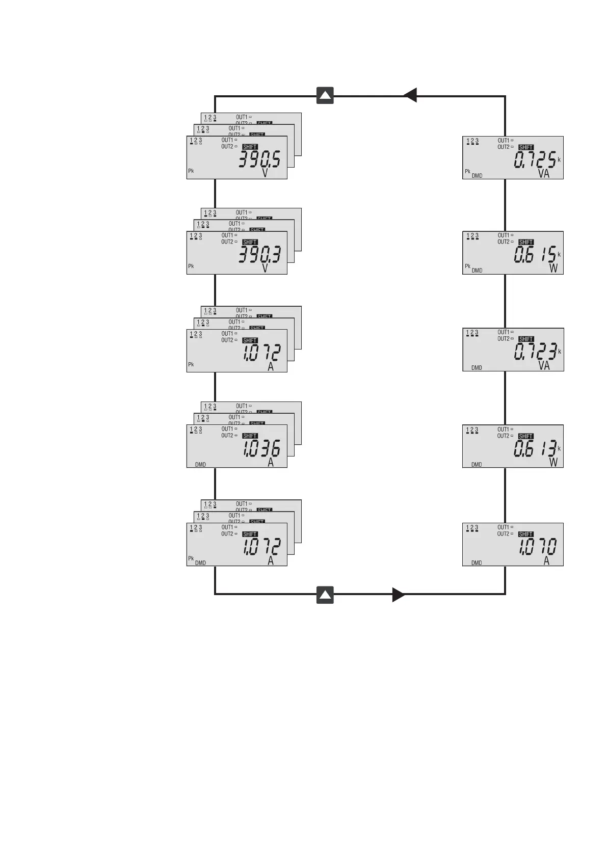
DMD & PEAK VALUES PAGES [3° loop] (optional)
Peak of system apparent power DMD [VA]
Peak of system active power DMD [W]
System apparent power DMD [VA]
System active power DMD [W]
System current DMD [A]
Peak of L-N phase 1 voltage [V]
Peak of L-N phase 2 voltage [V]
Peak of L-N phase 3 voltage [V]
Peak of L-L line 12 voltage [V]
Peak of L-L line 23 voltage [V]
Peak of L-L line 31 voltage [V]
Peak of phase 1 current [A]
Peak of phase 2 current [A]
Peak of phase 3 current [A]
Phase 1 current DMD [A]
Phase 2 current DMD [A]
Phase 3 current DMD [A]
Peak of phase 1 current DMD [A]
Peak of phase 2 current DMD [A]
Peak of phase 3 current DMD [A]
 Loading...