1. Display cable
2. Alien head LED-cable
3. Power-adapter cable
4. Right-fan cable
5. Speaker cable
6. Touchpad cable
7. Keyboard-controller board cable
8. Left-fan cable
9. Power-button cable
10.Camera cable
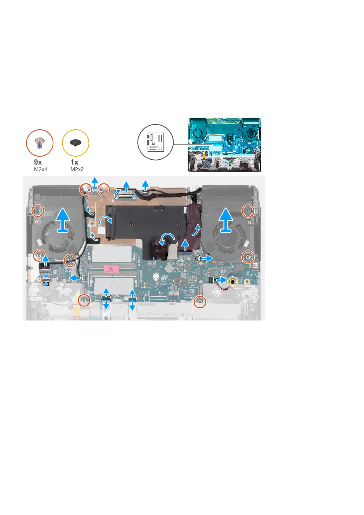
The following image(s) indicate the location of the system board and provides a visual representation of the removal procedure.
Steps
1. Remove the two screws (M2x4) that secure the Type-C bracket to the system board.
2. Lift the Type-C bracket off the system board.
3. Peel the tape that secures the display-cable connector latch to the system board.
4. Open the latch and disconnect the display cable from the system board.
5. Disconnect the Alien head LED-cable from the system board.
6. Peel the display cable off the system board and move it out of the way.
7. Lift the corner of the Mylar covering the system board.
8. Disconnect the power-adapter port-cable from the system board.
9. Peel the power-adapter port-cable from the Mylar.
10.Disconnect the right-fan cable from the system board.
11. Disconnect the speaker cable from the system board.
12. Open the latch and disconnect the touchpad cable from the system board.
13. Open the latch and disconnect the keyboard-controller board cable from the system board.
51