Do you have a question about the Alienware X51 R2 and is the answer not in the manual?
Details the front view of the Alienware X51 R2 computer, identifying key components and ports.
Details the back view of the Alienware X51 R2 computer, identifying key components and ports.
Provides information on where to find detailed computer configuration specifications online.
Provides step-by-step instructions on how to properly shut down and disconnect the computer and its peripherals.
Outlines essential safety guidelines to protect the computer from damage and ensure personal safety during operation.
Explains the purpose and functionality of the system setup utility for computer configuration.
Details the steps required to access the system setup utility during the computer's boot process.
Describes the layout and components of the system setup interface, including Setup Item, Help Screen, and Key Functions.
Lists and describes various configuration options available within the system setup, categorized by function.
Details the various boot options available, including Floppy, Hard Drive, CD/DVD, USB, and Network devices.
Explains how to temporarily change the boot sequence for a single boot instance, e.g., to boot from a USB device.
Provides instructions on how to permanently alter the boot device priority for all future system boots.
Lists relevant websites for obtaining the latest information, FAQs, and solutions for the Alienware computer.
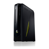
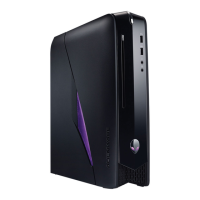
The Alienware X51 R2 is a compact gaming desktop computer designed for both vertical and horizontal orientation, offering flexibility in how it can be placed within a user's setup. Its front panel features essential user interaction points, including a power button, an optical drive with an eject button, and a rotatable AlienHead logo that adjusts to the computer's orientation. For audio connectivity, it provides a microphone port and a headphone port, alongside two USB 3.0 ports for high-speed data transfer.
The rear of the Alienware X51 R2 is equipped with a comprehensive array of ports to support a wide range of peripherals and network connections. It includes two USB 3.0 ports and two USB 2.0 ports for general connectivity, as well as an optical S/PDIF port and a coaxial S/PDIF port for digital audio output. For surround sound setups, there are dedicated rear L/R, side L/R, and center/subwoofer LFE surround ports, along with a microphone port and a line-in port for audio input, and a line-out port for stereo audio output. Video output is handled by an HDMI port and a discrete graphics card, allowing for connection to various display devices. Network connectivity is provided by a network port with integrated network lights. A hard-drive activity light indicates storage operation, and a security-cable slot is available for physical security. The power adapter port is located at the rear for connecting the external power supply. A label tab is also present, likely for identification purposes.
Before working inside the computer, it is crucial to follow specific safety guidelines to prevent data loss, hardware damage, personal injury, or even death. Users are advised to save and close all open files and programs, then properly shut down the computer through the operating system. All electrical and network cables, as well as attached devices, must be disconnected. Holding the power button while the computer is unplugged helps to ground the system board, further enhancing safety. Only certified service technicians are authorized to remove the computer cover and access internal components. When disconnecting cables, it's important to pull on the connector or its pull-tab, not the cable itself, and to ensure proper alignment to avoid bending pins. Network cables should be unplugged from the computer first, then from the network device. If applicable, any security cable should be removed from its slot. The work surface should be flat and clean to prevent damage to the computer.
The system setup (BIOS) provides a crucial interface for managing the computer's hardware and configuration. It allows users to view information about installed hardware, such as RAM and hard drive size, and to modify system configuration settings. Users can set or change options like user passwords and enable or disable base devices. However, caution is advised when changing these settings, as incorrect modifications can lead to system malfunction. Before making any changes, it is recommended to note down the current system setup screen information for future reference. To access the system setup, the user needs to turn on or restart the computer and press the F2 key immediately when the Alienware logo appears and the F2 prompt is displayed. If the F2 prompt is missed, the user must wait for the operating system to load, then shut down the computer and try again.
The system setup screen is divided into three main areas: the Setup Item, the active Help Screen, and Key Functions. The Setup Item lists configurable features, while the Help Screen provides detailed information about each highlighted option and its available settings. Key Functions displays the keys and their roles within the active setup field. Within the "Main" section of the system setup, users can view the system date and time, BIOS version and build date, product name, and enter or view the service tag and asset tag. The "ME Information" section displays the Management Engine (ME) Firmware version. "Memory Information" provides details on total memory, available memory, memory technology, and speed. "CPU Information" shows the processor ID, speed, and L2/L3 cache sizes. "Device Information" lists devices connected to SATA ports and mSATA devices.
The "Advanced - Advanced BIOS Features" section allows users to display or hide the RAID option ROM screen during POST. Under "Advanced - CPU Configuration," options include enabling or disabling XD Bit Capability, which helps the processor distinguish between executable and non-executable code. Intel(R) SpeedStep Technology can be enabled or disabled to dynamically adjust processor clock speed and core voltage based on load. CPU C states can also be enabled or disabled. In "Advanced - Integrated Devices," users can enable or disable the integrated USB controller, integrated audio controller, and onboard LAN controller. The "Primary Display" option allows selection of the integrated or discrete graphics device as the primary display. For network booting, "UEFI PXE Driver" enables or disables the boot option for UEFI network devices. "PCIE Gen3" allows enabling or disabling PCIE Gen3 capability. Under "Advanced - Power Management Setup," "AC Recovery" sets the computer's action upon power restoration.
The "Security" section provides options for managing passwords. Users can view the status of the Supervisor and User Passwords, set or change a supervisor password, and set or change a user password (only if a supervisor password is already set). "Boot Menu Security" can be enabled or disabled, but this option is only displayed if a supervisor password has been set. The "Boot" section covers boot configuration. "Bootup NumLock State" allows enabling or disabling the keyboard NumLock state at boot. "Wait For 'F1' If Error" determines if the system halts during boot to display errors. "Secure Boot Control" enables or disables secured booting, and "Load Legacy OPROM" allows enabling or disabling the Legacy Option ROM.
"Set Boot Priority" offers the choice between Legacy or UEFI boot mode. Legacy mode supports booting to devices with Legacy BIOS, while UEFI mode supports UEFI drivers. A critical caution is provided regarding changing boot modes: the boot storage device must be partitioned to match the chosen boot mode's compatibility. Incorrect changes can lead to an incompatible boot storage device, preventing the original OS from booting. Restoring the boot mode may resolve such issues. "USB Boot Support" enables or disables booting from USB mass storage devices like hard drives, optical drives, and flash drives. The system setup also displays the first through fifth boot devices, with defaults like UEFI:Windows Boot Manager, USB Hard Disk, CD/DVD, Floppy, and Network. "Hard Disk Drive BBS Priorities" dynamically updates and sets the boot priority for detected hard drives. Finally, the "Exit" options allow users to save changes and reset, discard changes and reset, or restore defaults.
The boot sequence feature allows users to change the order in which the computer attempts to boot from different devices. Options include Floppy, Hard Drive, CD/DVD/CD-RW Drive, USB Storage Device, and Network. If a device is not bootable or lacks an operating system, an error message is generated. To boot from a USB device, it must be connected and bootable, and the user must press F12 during POST to access the Boot Options menu. This feature is useful for temporary changes, such as booting from an optical drive to run diagnostics. The previous boot sequence is restored after a temporary boot. For permanent changes to the boot sequence, users must enter system setup, navigate to "Boot," and then "Set Boot Priority" to reorder the boot devices. It is recommended to write down the current boot sequence before making changes.
Flashing the BIOS is a maintenance task that may be required for updates or when replacing the system board. The process involves several steps: turning on the computer, navigating to dell.com/support/downloads, and selecting "Drivers & Downloads Home" under "Support for Home Users." Users can then locate their computer's Service Tag (found on a label at the back of the computer) or Express Service Code and enter it to find specific drivers. Alternatively, if the Service Tag is unknown, users can choose to automatically detect it, select from a list of products, or browse all Dell products. After selecting the operating system, the user clicks "BIOS" from the results list, then "Download File" to get the latest BIOS file. In the "Choose Download Method" window, "Single-file download" is selected, and the file is saved to a chosen location on the computer. Once the download is complete, the user navigates to the saved file, double-clicks its icon, and follows the on-screen instructions to complete the BIOS update.
For support and service, Alienware provides online and telephone-based options, which may vary by country and product availability. Users can visit dell.com/contactdell to find appropriate service or support links and choose a convenient contact method. In the United States, Alienware users can call 1-800-ALIENWARE for assistance. For the latest information, FAQs, and solutions to common issues, the official website dell.com/Alienware serves as a valuable resource.
| Power Supply | 330W External Power Adapter |
|---|---|
| Chipset | Intel H87 |
| Memory | Up to 16GB DDR3 at 1600MHz |
| Graphics Options | AMD Radeon R9 270 |
| Storage Options | 2TB 7200RPM HDD or 256GB SSD |
| Optical Drive | Slot-Loading Dual Layer DVD Burner |
| Operating System | Windows 8.1 |
| Dimensions | 343 x 318 x 95 mm (13.5 x 12.52 x 3.74 inches) |
| Weight | 12.1 lbs (5.49 kg) |
| Networking | Gigabit Ethernet |
| Ports | HDMI, DisplayPort |
| Processor Options | 4th Generation Intel Core i5/i7 (Haswell) |