Do you have a question about the Alinco DJ-195 and is the answer not in the manual?
Details frequency coverage, mode, channel steps, memory, antenna, stability, power, current, temperature, dimensions, weight, DTMF, CTCSS, DCS.
Output power, modulation system, spurious emissions, and max frequency deviation.
Receive system, intermediate frequencies, sensitivity, selectivity, and audio output power.
Describes the double superheterodyne receiver system, including front end, IF circuit, demodulator, and audio circuit.
Covers modulator circuit, power amplifier circuit, and APC circuit functions.
Details the PLL system, including its main components like VCO, reference frequency, and phase comparator.
Explains CPU functions like LCD display, lamp, reset, S-meter, DTMF, CTCSS, and DCS encoding.
Shows the pinout and connections for the M3826M8L CPU.
Provides electrical characteristics and equivalent circuit for the NMJ2070M power amplifier.
Details the pinout and function for the AT24C16N serial EEPROM.
Shows the internal circuit diagram for the M5222FP electronic volume control IC.
Presents the block diagram and electrical characteristics for the TK14521MTL IF system IC.
Displays pinout information for the M64082AGP IC.
Shows the internal circuit and pinout for the NJM2904V dual op-amp.
Displays the internal circuit and pinout for the NJM2902V quad op-amp.
Provides the top view and circuit diagram for the S-81250SG voltage regulator.
Shows the top view and circuit diagram for the S-80845ALMP voltage regulator.
Displays outline drawings and identification markings for various transistors, diodes, and LEDs.
Illustrates the pin connections for the LCD module.
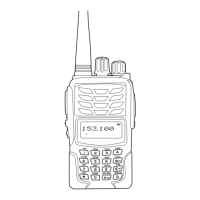
Shows an exploded view of the front components of the transceiver.
Displays an exploded view of the rear components and internal layout.
Lists electronic components and their part numbers for the main unit.
Lists mechanical components like screws, nuts, and rubber parts.
Lists packaging materials such as antennas, labels, and manuals.
Lists the necessary test equipment for adjusting the radio's parameters.
Details measurement conditions for linear detection, including modulation and sensitivity.
Explains how to enter adjustment mode and lists channel frequencies for adjustments.
Provides specific instructions for adjusting radio sensitivity using the CPU and tuning circuit.
Shows the component layout on the main PCB, side A.
Displays the component layout on the main PCB, side B.
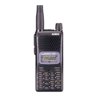
| Modulation | FM |
|---|---|
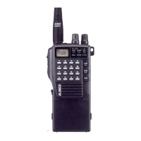
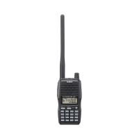
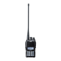
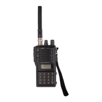
| Antenna Connector | BNC |
| Type | Handheld |
| Frequency Range | 136-174 MHz |
| Output Power | 5W |
| Channel Steps | 5kHz / 10kHz / 12.5kHz / 25 kHz |
| Battery | Li-ion Battery |