3
2
Red
Black
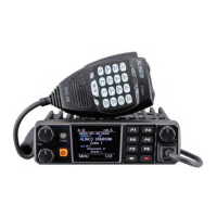
Initial Installation
6.
Connect the DC power cable to the transceiver's power supply
connector.
Press the connectors rmly together until the locking tab clicks.
Ext. Power jack
DC power cable
In order to use this transceiver for xed station operation, you will need
a separate 13.8V DC power supply (not included), Please contact local
dealer to require.
Fixed Station Operation
DC Power Cable Connection
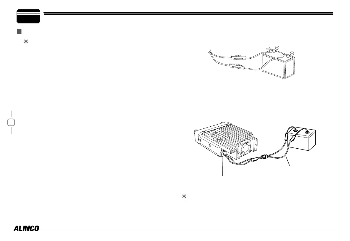
Mobile Operation
The vehicle battery must have a nominal rating of 12V. Never
connect the transceiver to a 24V battery. Be sure to use a 12V
vehicle battery that has sufficient current capacity. If the current
to the transceiver is insufficient, the display may darken during
transmission, or transmitting output power may drop excessively.
1.
Route the DC power cable supplied with the transceiver directly
to the vehicle's battery terminals using the shortest path from the
transceiver.
Never use the cigarette lighter socket as a DC source.
The entire length of the cable must be dressed so it is
isolated from heat, moisture, and the engine secondary (high
voltage) ignition system/cables.
2.
After installing cable, in order to avoid the risk of damp, please
use heat-resistant tap to tie together with fuse box. Don't forget
to reinforce whole cable.
3.
In order to avoid the risk of short circuit, please cut down
connection with negative (-) of battery, then connect with
transceiver.
4.
Conrm the correct polarity of the connections, then attach the
power cable to the battery terminals; red connects to the positive
(+) terminal and black connects to the negative (-) terminal.
Never remove the fuse holders from the cable.
5.
Reconnect any wiring removed from the negative terminal.