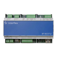
3 Mounting the controller
© 2021 Interflex Datensysteme GmbH IF-4072 Controller 9
3 Mounting the controller
NOTICE
Damage to property due to manipulation of the controller
Manipulation of the controller can lead to data loss.
u Install the controller in the secured area, taking the technical requirements into account
u Mount the controller on a TS35 DIN rail, e.g. in a distribution box.
4 Connecting the controller
4.1 Wiring components
The cables can be fixed to the cutouts in the bottom plate of the housing with cable ties.
Ethernet network
The device is set up for connection to 10/100 Mb/s Ethernet networks. Connection and speed are
indicated by LEDs on the front panel LEDs and switches.
When assigning the IP address and setting up the network, observe the current state-of-the-art
technology for securing and segmenting corporate networks. Interflex recommends operating all
installed devices and servers in one VLAN.
Bus data cables with readers
You can connect up to 8 readers to each bus interface. A maximum of 16 readers can be
connected to the controller.
n
Always connect a reader with address 1 to bus 1.
n
Evenly distribute the readers among the three bus interfaces. The factory setting for the
interfaces is as follows:
– Bus 1: 6 readers max.
– Bus 2: 4 readers max.
– Bus 3: 6 readers max.
Make sure that each reader has a unique hardware address within the bus.