18 DR66 & DR128 Installer User Guide
Calibration Adjustments Available
DR66
Parameter Adjust Factory Default Setting
Mic Input Gain 1-2 Internal trimmer Gain minimum Fully anti-clockwise
Mic/Line Pad 1-2 Pair of internal links Pad disabled (Mic) Links fitted
Mic Phantom Power 1-2 Internal link Phantom Power On Link fitted
Line Input Level 3-6 Internal link -10dBV sensitivity Link not fitted
Line Output Level 1-6 Internal link +4dBu nominal Link not fitted
DR128
Parameter Adjust Factory Default Setting
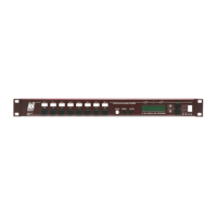
Mic Input Gain 1-8 Rear panel trimmer Gain minimum Fully anti-clockwise
Mic/Line Pad 1-8 Pair of internal links Pad disabled (Mic) Links fitted
Mic Phantom Power 1-8 Internal link Phantom Power On Link fitted
Line Input Level 9-12 Internal trimmer -10dBV sensitivity Fully clockwise
Line Output Level 1-8 Internal trimmer +4dBu nominal Fully anti-clockwise
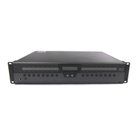
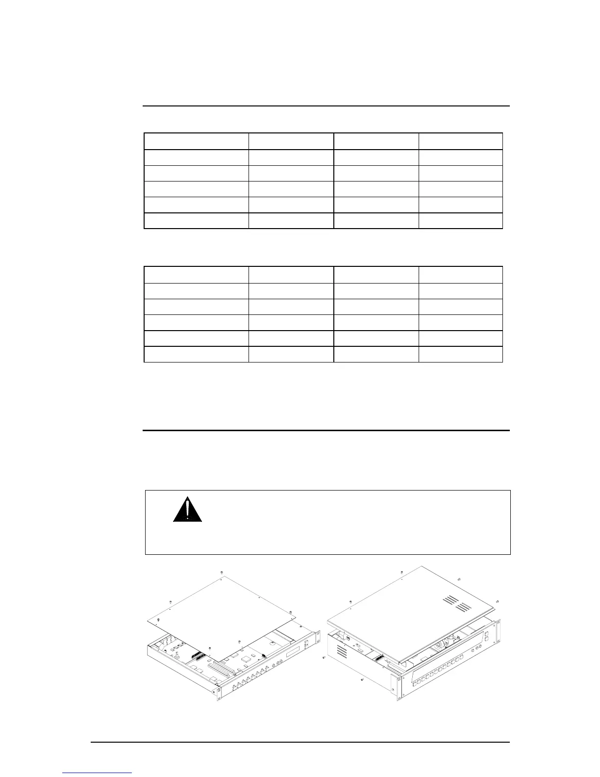
Removing the Top Cover
The DR hardware is configured by setting internal jumper links and calibration trimmers. Optional
cards can be plugged into circuit board slots to expand the DSP processing power. To access
these remove the top cover using a crosspoint screwdriver to remove the fixing screws. Slide the
cover back and carefully lift it off. Refit the cover after configuration.
WARNING: Do not remove the power unit covers. Remove and refit the
top access cover and reposition the internal jumper links with power to the unit
switched off. Only apply power when calibrating the audio signal levels.
 Loading...