DR66 & DR128 Installer User Guide 19
Labelling the Function Keys
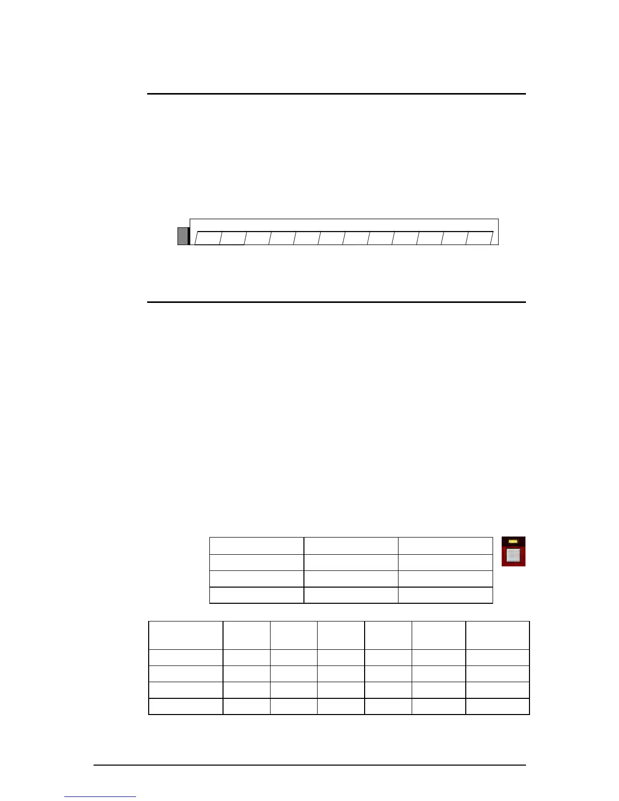
DR66 Write-on blocks are provided above each of the 8 function keys. Use permanent pen or
pre-prepared adhesive labels to identify the key functions. A log sheet to keep a record of the
functions is provided at the rear of this user guide.
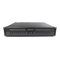
DR128 The front panel facia plate can be removed so that a label can be fitted behind the
window above the 12 function keys. This ensures that the key identification is tamperproof. Use a
2mm hex key to remove the four corner hex fixing screws. This can be done with the unit installed
in its rack or furniture. A Windows
®
Word
®
template is provided with the WinDR software. It is
also printed together with fitting instructions and installer log sheet at the rear of this user guide.
Working with Audio Signal Levels
When calibrating the unit it is advised to have a PC running WinDR so that you can use the full
range channel meters to set the optimum input and output operating levels. These are high
resolution dBFS bar meters that display signal up to maximum output level. Alternatively, the front
panel LED indicators could be assigned as input or output level meters to show basic signal
presence, nominal level and peak.
0dBFS 0dB Full Scale is the maximum internal signal level before clipping. To avoid distortion
the signal that is passed through the ADC and DAC should not exceed this maximum. For this
reason calibration trimmers are provided to match the source to the DR input stage, and to match
its output to the destination equipment.
While the dynamic range is the signal capability from noise floor to clipping level, the signal-to-
noise performance is determined by the nominal (normal) operating level. The higher you make
this level the better the noise performance but the less the headroom. It is typical to provide at
least 10dB of headroom above the nominal level to allow for unexpected signal peaks and loud
moments. The DR front panel meters (if assigned) are calibrated for a nominal level allowing 12dB
of headroom. Of course, you can operate the unit at lower or higher level if you wish to allow more
or less headroom. It is important that the relationship between the internal 0dBFS and the output
dBu level is understood.
Meter Green Meter Amber Meter Red
Signal presence Nominal level Signal peak
Channel active Normal loud Approaching clipping
-36dBFS -12dBFS -6dBFS
Operating
Level
Output
Setting
Meter
Green
Meter
Amber
Meter
Red
Clip Headroom
-10dBV (-8dBu) -10 -32dBu -8dBu -2dBu +4dBu 12dB
0dBu 0 -24dBu 0dBu +6dBu +12dBu 12dB
0dBu +4 -20dBu +4dBu +10dBu +16dBu 16dB
+4dBu +4 -20dBu +4dBu +10dBu +16dBu 12dB
 Loading...