L2SM2
ALLEN & HEATH
12
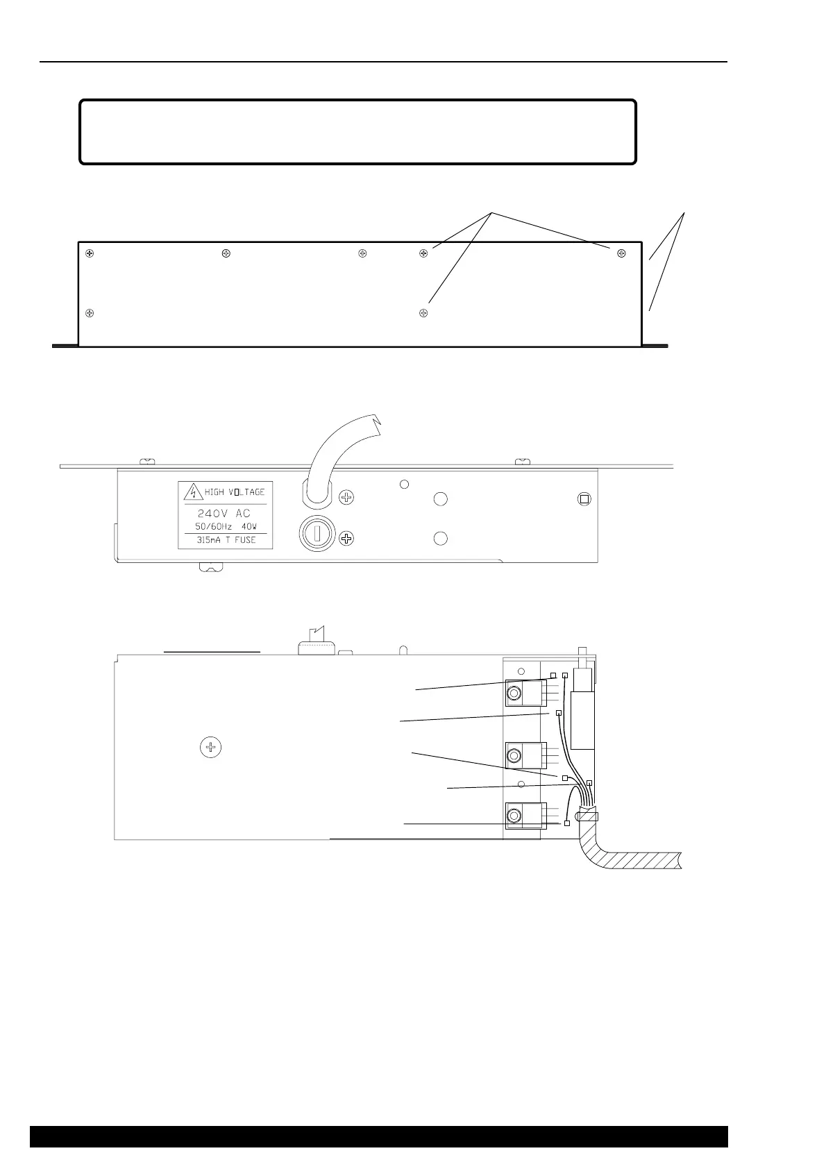
REMOVE THE 3x REAR
POWER UNIT M3 SCREWS
REMOVE THE 2x
SIDE M3 SCREWS
PRECAUTIONS ! Disconnect the console from the mains supply before removing the power
unit. Servicing of the power unit should only be carried out by technically competent personnel.
DANGER - HIGH VOLTAGE !
PRECAUTION ! Check that the console DC harness wires are soldered to the
correct power unit pins before switching the console on. Ensure good solder joint. Re-
tin the pins if necessary.
PRECAUTION ! Check that the power unit is set for the correct local mains voltage
supply before switching the console on.
LIFT THE POWER UNIT OUT OF THE BASE. BE CAREFUL
NOT TO TRAP THE ATTACHED CONSOLE DC HARNESS
WHEN REMOVING OR REPLACING THE POWER UNIT.
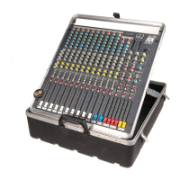
REMOVING THE POWER UNIT
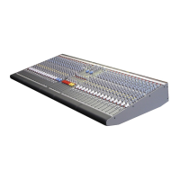
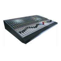
The power unit is common to both the GL2 and GL2-S. The power unit may be removed for servicing with the base in place.
CONSOLE DC
HARNESS ON
THIS SIDE
The console internal DC harness connects the power unit output to the channel assemblies. The harness runs between channels
8 and 9 and along the ribbon cable recess to the Master circuit assembly. The wires are soldered to the power unit to ensure
low impedance connections for power distribution. The harness allows enough service loop for the power unit to be lifted clear
of the console for service work. To replace the unit it is necessary to desolder the wires.
0V GREEN WIRE
+16V RED WIRE
-16V BLACK WIRE
CHS GREEN/YEL WIRE
+48V BLUE WIRE
 Loading...