Rockwell Automation Publication 1734-UM001E-EN-P - July 2013
84 Install POINTBlock I/O Modules
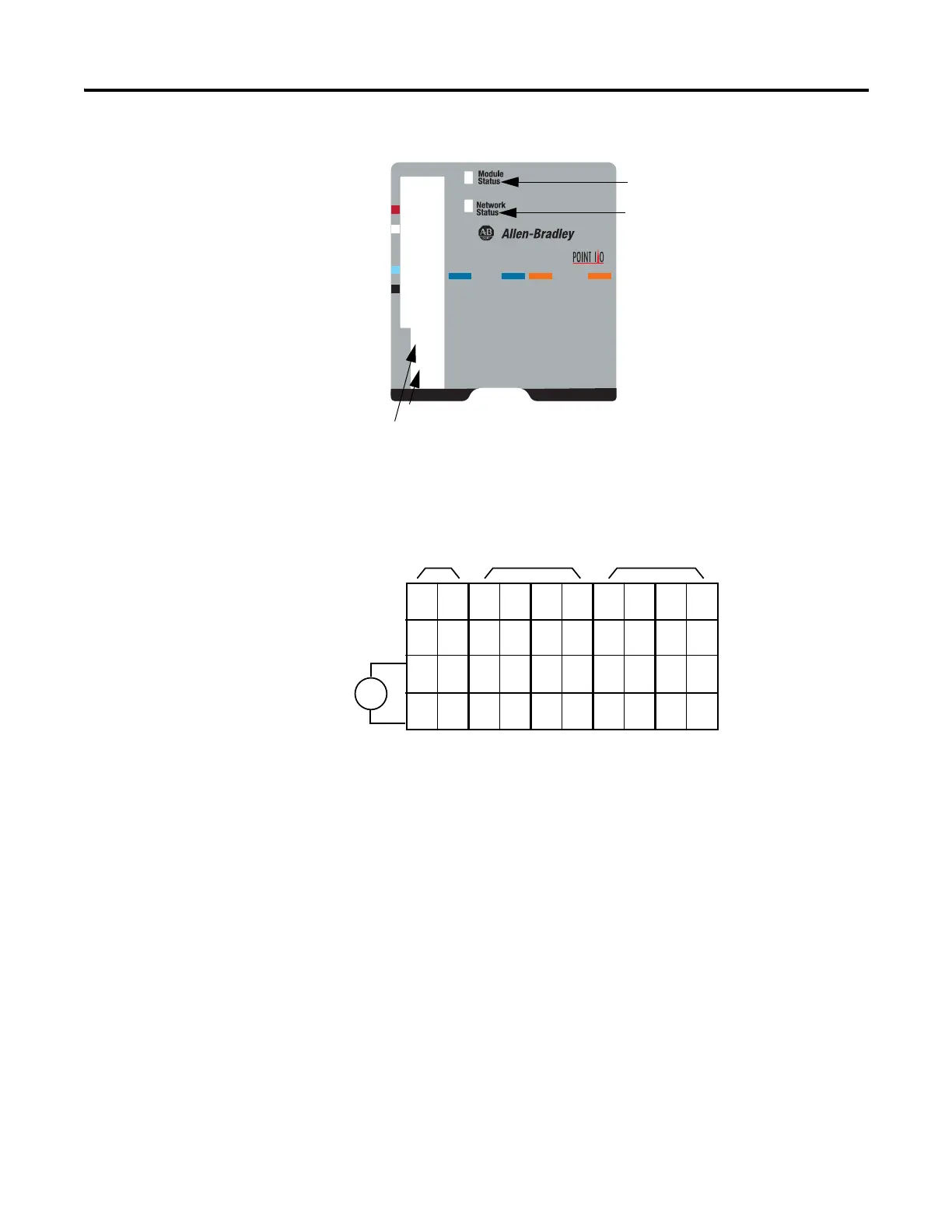
1734D-IA8XOA8 POINTBlock 8 AC In/8 AC Out Modules
1734D-IA8XOA8 POINTBlock 8 AC In/8 AC Out Modules Wiring
Diagram
0
1
2
3
4
5
6
7
0
1
2
3
4
5
6
7
0-9
10-60
Inputs
Outputs
42004
10’s Node Address Rotary Switch
1’s Node Address Rotary Switch
Module Status
Network Status
I/O status
V ac
NC
NC
L2in
L1in
120V ac
Power
NC = No Connection Chas Gnd = Chassis Ground
L2/N = AC Return/Neutral L1 = AC Power
NC
NC
0
2
L2
L1
1
3
L2
L1
4
6
L2
L1
5
7
L2
L1
0
2
L2
L2
1
3
L2
L2
4
6
L2
L2
5
7
L2
L2
Field Power
Inputs Outputs
L1in
L2in
This supply will be connected to the internal power bus.
RTB 0 RTB 1 RTB 2 RTB 3 RTB 4
01
23
45
67
01
23
45
67
01
23
45
67
01
23
45
67
01
23
45
67

 Loading...


