14 Compact I/O High-speed Counter Module
Publication 1769-IN030B-EN-P - October 2010
Grounding Guidelines
•
This product is intended to be mounted to a well-grounded mounting surface, such as a
metal panel. Additional grounding connections from the module’s mounting tabs or
DIN rail (if used) are required only when the mounting surface is non-conductive and
cannot be grounded.
• Keep shield connection to ground as short as possible.
• Ground the shield drain wire at the 1769-HSC module’s input end only.
Refer to the Industrial Automation Wiring and Grounding Guidelines,
publication 1770-4.1
, for additional installation requirements
Terminal Block Guidelines
•
For optimum accuracy, limit overall cable impedance by keeping cable as short as
possible. Locate the module as close to input devices as the application permits.
• Tighten terminal screws with care. Excessive tightening can strip a screw.
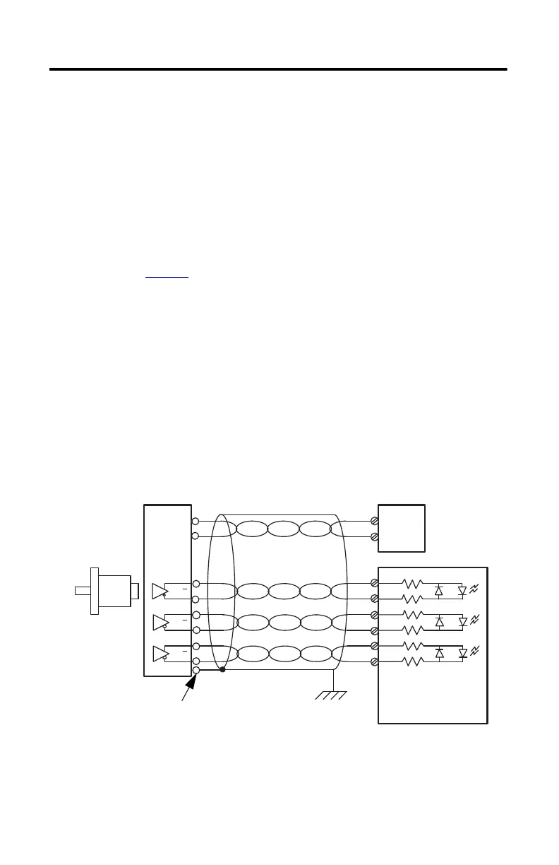
Wire Diagrams
The following pages show wiring examples for a differential encoder, single-ended encoder,
and discrete device.
Figure 4 - Differential Encoder Wiring
(1) Refer to your encoder manual for proper cable type. The type of cable used should be twisted-pair, individually shielded
cable with a maximum length of 300 m (1000 ft).
A
A
B
B
Z
Z
A1(+)
A1(–)
B1(+)
B1(–)
Z1(+)
Z1(–)
GND
VS
+VDC
COM
Cable
(1)
Power
Supply
Allen-Bradley
845H Series
Differential
Encoder
Shield/Housing
Connect only if housing is electronically
isolated from the motor and ground.
Shield
Module Inputs
Earth

 Loading...


