Compact I/O High-speed Counter Module 15
Publication 1769-IN030B-EN-P - October 2010
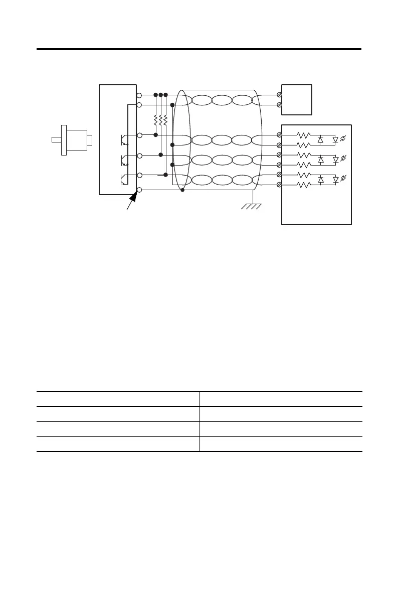
Figure 5 - Single-Ended Encoder Wiring
(1) Refer to your encoder manual for proper cable type. The type of cable used should be twisted-pair, individually shielded
cable with a maximum length of 300 m (1000 ft).
(2) External resistors are required if they are not internal to the encoder. The pull-up resistor (R) value depends on the power
supply value. The table shows the maximum resistor values for typical supply voltages. To calculate the maximum resistor
value, use the following formula:
where:
R = maximum pull-up resistor value
V DC = power supply voltage
V min = 2.6V DC
I min = 6.8 mA
The minimum resistor (R) value depends on the current sinking capability of the encoder. Refer
to your encoder’s documentation.
Power Supply Voltage (V DC) Pull-up Resistor Value (R), Max
(1)
(1) Resistance values may change, depending upon your application.
5V DC 352 Ω
12V DC 1382 Ω
24V DC 3147 Ω
A
B
Z
A1(+)
A1(–)
B1(+)
B1(–)
Z1(+)
Z1(–)
GND
VS
+VDC
COM
R
(2)
Cable
(1)
Power
Supply
Allen-Bradley
845H Series
Single-ended
Encoder
Shield/Housing
Connect only if housing is electronically
isolated from the motor and ground.
Shield
Module Inputs
Earth
R
VDC Vmin–
Imin
-------------------------------------------=

 Loading...


