16 Compact I/O High-speed Counter Module
Publication 1769-IN030B-EN-P - October 2010
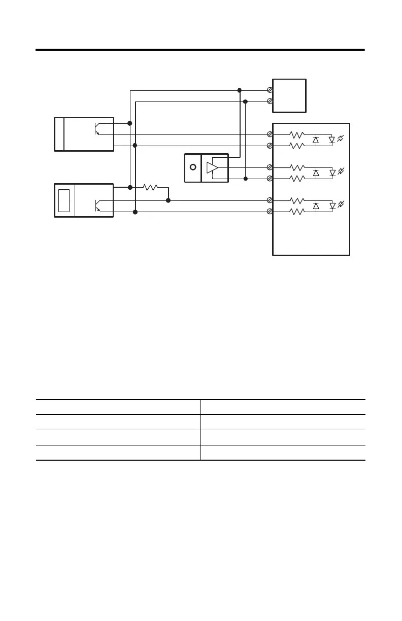
Figure 6 - Discrete Device Wiring
(1) External resistors are required if they are not internal to the sensor. The pull-up resistor (R) value depends on the power
supply value. The table shows the maximum resistor values for typical supply voltages. To calculate the maximum resistor
value, use the following formula:
where:
R = maximum pull-up resistor value
V DC = power supply voltage
V min = 2.6V DC
I min = 6.8 mA
The minimum resistor (R) value depends on the current sinking capability of the sensor.
Refer to your sensor’s documentation.
Power Supply Voltage (V DC) Pull-up Resistor Value (R), Max
(1)
(1) Resistance values may change, depending upon your application.
5V DC 352 Ω
12V DC 1382 Ω
24V DC 3147 Ω
VS
A1(+)
A1(–)
B1(+)
B1(–)
Z1(+)
Z1(–)
+VDC
COM
VS
OUT
COM
OUT
COM
VS
OUT
COM
R
(1)
Power
Supply
Module Inputs
Solid-state
Switch
Proximity Sensor
Photo-electric Sensor with
Open Collector Sinking
Output
R
VDC Vmin–()
Imin
---------------------------------------------=

 Loading...


